What Is a Low Pass Filter? Understanding an Electronic Filter Circuit
2025-01-15 | By Don Wilcher
A circuit that allows specific frequencies below a target or cutoff frequency while minimizing higher signals is known as a low-pass filter. The low-pass filter is widely used in electronic circuits and signal-processing applications. Control systems depend on low-pass filters to stabilize electromechanical oscillations through a specialized tuning controller. High-voltage DC power supplies rely on low-pass filters to remove electrical noise transients induced by the vibration of a power transformer’s windings or electronic switching devices like transistors and clock circuits. This article will discuss the low-pass filter's theory, operation, and circuit design, as well as the explanation of attenuation and specifics of the resistor and the capacitor’s electrical behavior.
What Is a Low Pass Filter?
A low-pass filter is an electronic circuit that removes high-frequency components from a signal. A low-pass filter only allows certain frequencies below a specific threshold to pass. The threshold is the cut-off frequency (fc) which indicates the point where high-frequency signals begin to be reduced. A minimized signal level in amplitude is called attenuation. With the high-frequency signals being attenuated, the low-frequency can pass with minimal reduction. Shaping the signals by eliminating unwanted high-frequency noise like rf transients is the function of the low-pass filter. Audio systems, laptop computers, industrial controls, Wi-Fi Bluetooth devices, and other sensitive electronic products use a low-pass filter to eliminate electrical noise that can disrupt the performance of these systems. A low-pass filter can be built using passive electronic components like resistors, capacitors, or inductors.
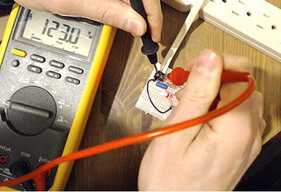
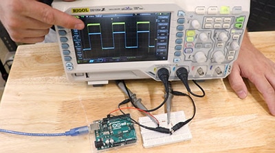
 A low-pass filter built from an electronics project kit.
The word passive describes a circuit that does not require an external power supply to operate. The common low-pass filter used is the resistor-capacitor (RC) circuit. With the addition of a transistor or operational amplifier (op-amp), the electrical signals produced by a passive low-pass filter can be amplified by these active electronic components. An active low-pass filter requires an external power supply to energize the transistor or operational amplifier component to amplify the clean signal.
 An active low-pass filter circuit using an operational amplifier.
The Low Pass Filter Operation: Key Concepts
The primary operation of a low-pass filter is to attenuate high-frequency signals and pass low-repetitive signals. Several key concepts impact the low-pass filter’s electrical operation. Three such key factors that allow the low-pass filter to attenuate high-frequency signals are listed below.
1. Frequency Response - Attenuating frequencies above a certain threshold value or cutoff frequency is achieved by the selection of the low-frequency filter electronic components. The selection of the electronic components will define the reduction in the high-frequency signal applied to the low-pass filter. The final output response is the reduction in amplitude of the high-frequency signal injected into the low-pass filter’s input terminals.
2. Cutoff Frequency – This threshold value is the frequency established by the selection of the passive electronic components at which the filter transitions from attenuation to signal passing of frequencies. To determine the cutoff frequency (fc) of an RC low-pass filter, the following equation is used.
 Cutoff Frequency (fc) equation for passive RC Low Pass Filter.
3. Impedance – A capacitor’s impedance or reactance (Z) can affect a low-pass filter’s operation. Impedance is the resistance to AC signals within an electrical circuit. The electrical unit for impedance is the ohm. Capacitive reactance (Xc) is another term used to describe a capacitor’s impedance. When low frequencies (f) are applied to a capacitor, its impedance or reactance will be high. At high frequencies, the reactance or impedance will be low. A capacitor’s impedance or reactance is high when low frequencies are applied. The high-frequency signals will be attenuated or minimized due to the capacitor's low impedance in the circuit.
where:
f is the injected applied frequency to the low-pass filter
C is the capacitor value used in the low-pass filter
 Determining a capacitor’s impedance using the Capacitive Reactance equation.
Click here to visit the DigiKey Low Pass/High Pass Filter Calculator!
Attenuation Is Important in Signal Processing
The reduction in signal strength in an electrical or electronic circuit is attenuation. In designing amplifiers, signal processing is important to reduce or potentially eliminate the electrical hum or noise that can affect the audio quality of the amplifier. A low-pass filter aids in the reduction of the electrical disturbance by attenuating the signal’s amplitude based on the existing high-frequency components. Attenuation is measured in the unit of decibels (dB). The decibel is a logarithmic unit that represents the ratio of output signal amplitude to input signal amplitude.

In the attenuation equation, Vout is the output voltage measured across the capacitor of the low-pass filter. The input voltage, Vin, is the signal applied or injected into the low-pass filter. A resultant dB value that is positive indicates an increase or amplification in signal strength. A negative dB value implies a reduction in output signal strength. Therefore, a negative dB value indicates attenuation, and a high-frequency signal has been rejected by the low-pass filter.
Low Pass Filter Key Characteristics
The low-pass filter is a reliable electronic circuit that performs the role of attenuating high-frequency signals. To accomplish these minimization tasks requires several important performance attributes or characteristics from the filter circuit. The key characteristics of the low-pass filter are listed next.
Key Characteristics
1. Cutoff Frequency (fc): The frequency at which the filter’s output signal power is half reduced in the amplitude of its input signal power is known as the fc. Another parameter used to describe this attenuated amplitude power level is -3 decibels (dB).
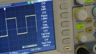
 A low-pass filter attenuated a 1 kHz signal. Note: V(N02) is the input signal, and V(N03) is the output signal.
2. Passband: The frequency range that is below the cutoff frequency where signals pass easily with minimal attenuation is called the passband.
3. Stopband: The range of frequencies that are above the cutoff frequency and attenuated is the stopband.
4. Roll-Off: The rate at which the low-pass filter reduces the signals beyond fc. First-order filters have a roll-off of -20 dB per decade. Second-order filters have a roll-off of -40 dB per decade.
The order of filters is based on the number of capacitors used in the circuit. A second-order filter uses two capacitors, while a third-order circuit uses 3 passive charging electronic components. To illustrate the characteristics of the low pass filter, a frequency response curve is used to plot these key parameters. The frequency response curve is an important engineering tool used to design or analyze the low-pass filter circuit's electrical performance.
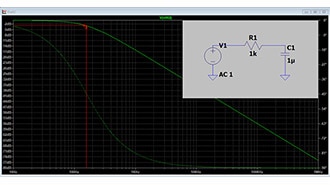
 An example low-pass filter frequency response curve. Plot based on an R-value of 50KΩ and C-value of 0.01uF.
With circuit simulation software and modeling tools, the key characteristics of a low-pass filter can be evaluated. This evaluation step in the design of low-pass filters will ensure proper attenuation and filtration of unwanted signals can be achieved successfully. Further, using the software resources will ensure the physical circuit will work as designed with minimal errors detected.
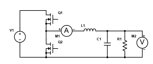
 A low-pass filter circuit simulation model.
The Active Low Pass Filter (LPF)
In contemporary electronic products, the op-amp is used along with resistors and capacitors to create an LPF. The op-amp enhances the performance of the LPF by providing the appropriate amount of amplification. The low-pass filter provides several advantages over the passive design. Some advantages offered by the active LPF over the passive circuit are gain, better performance, and impedance (Z) matching. The following list of additional advantages of the active LPF.
Circuit Description
- A resistor wired in series with an output capacitor attached to the non-inverting pin of an op-amp.
- The op-amp provides amplification and buffering for the low-pass filter.
Advantages of Active LPFs:
- Gain Control: The Active LPF amplifies the output signal based on the electronic product’s requirements and design specifications.
- Impedance (Z) Matching: To ensure one electronic circuit does not load down the performance of another circuit, the active LPF can provide proper impedance matching.
- Precision: By selecting the appropriate op-amp with a frequency compensation feature, accurate cutoff frequencies and better attenuation/frequency response characteristics can be achieved with an active LPF.
Conclusion
Low-pass filters are essential circuits that allow control over frequency components of an electrical signal to pass in electronic products or systems. By selecting the appropriate resistor-capacitor components, attenuating high-frequency noise and signal disturbances can be achieved. These filters can provide clean signals, thereby making them useful in audio, communication, imaging, power supply conversion, and test measurement applications. Furthermore, understanding attenuation and the role of the resistor-capacitor circuit arrangement in an RC low pass filter provides knowledge on effectively managing electrical disturbances in various electronic applications.