Avoid These Common Mistakes in Your Digital Electronic Projects
2022-01-31 | By Maker.io Staff
A previous article investigated some of the biggest mistakes new makers make. That article looked more at the general side of electronics projects, and it reminded me of a few common problems that frequently occur in digital electronics projects. This article summarizes a few common mistakes I’ve seen over the years, and I hope it helps you avoid a few of the most common pitfalls when working with digital electronics.
Missing Smoothing Capacitors
If you’ve worked with more elaborate digital electronic ICs, such as more sophisticated microcontrollers, you may have noticed that your project behaves erratically under specific conditions. Sometimes, it’s difficult to reproduce the errors, and they seem random at times. If these problems sound familiar to you, you might have forgotten to add an appropriately sized smoothing capacitor near the power pins of one or more ICs.
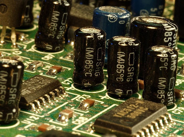
 Various capacitors near some ICs.
Some integrated circuits, such as microcontrollers, work just fine without these capacitors under certain conditions. However, a more complex program could force the microcontroller to draw more power for a short time. Depending on the power supply, these sudden current spikes could reduce the IC's input voltage. When that happens, the MCU might power down or reset itself. This behavior is commonly referred to as a brown-out.
Therefore, it’s important that you add an appropriately sized capacitor near the power pins of the affected ICs. This way, the capacitor can quickly supply the MCU with the extra power it requires, which leaves the power supply with enough time to catch up. Look at the chip’s datasheet to learn more about the recommended capacitor value.
Incorrect Clock Values and Other Timing-Related Issues
When you think about the clock as the heartbeat of a digital circuit, you can imagine how important a steady and accurate clock signal is to a successful digital electronics project. Try using high-quality quartz oscillators as a reliable and precise base clock, and derive other clock signals from the source as needed.
Apart from accuracy and stability, you should also ensure that the clock signal meets the requirements of the ICs in your design. The most obvious limitation is the clock frequency. Most ICs will work just fine with a slow clock signal, and you can often turn off the clock to pause the circuit. However, using too high clock frequencies might cause weird and hard to reproduce errors that are also difficult to trace.
If your project communicates with other digital electronic circuits (for example, a graphics display), you should carefully pick a clock source that matches both circuits’ requirements. Slight deviations might already be too much, and the communication might fail, as the data doesn’t arrive when it’s supposed to.
Apart from the clock signal, there are many other timing-related variables to keep in mind. Prominent examples include propagation delay, setup, and hold-times. Without going into too much detail, these timings can quickly ruin your digital project. When you design a schematic with multiple digital components, you might be tempted to assume that state changes are instant. However, consider the following example:
 This example illustrates different signal run times in a small digital circuit that only uses a handful of logic gates.
Each of the gates in this digital circuit will take some time before producing a valid result at the output. This is the so-called propagation delay. In addition, each input needs to be stable (i.e., not change from HIGH to LOW or vice versa) for a fixed period to ensure that the output is correct. The larger your circuit gets, the more these timings may become a problem if you don’t pay attention to them. In the image above, you can see that the circuit computes output B using three NAND-gates. Output A, on the other hand, requires more computational steps. Thus, it will take a real circuit longer to compute A than B, and you should consider that fact in subsequent parts of your design to prevent errors.
Pay Attention to the Voltage Levels in Your Circuit
The most common voltage levels in DIY projects are 3.3V and 5V. Make sure that you don’t mix components that use different voltages without using something like a logic-level-converter. Sometimes, mixing voltages might not result in an immediate problem, as most ICs can tolerate slightly higher or lower input voltages just fine. However, logic signals must typically be between certain limits for the devices to recognize them as either HIGH or LOW. Typically, voltages below 0.7V represent LOW signals, while voltages above 2.2V are considered HIGH. However, you should always check the datasheets of the components in your design for the exact specifications. Either way, some 5V devices might not detect a 3.3V signal as a HIGH input, which results in incorrect behavior of your circuit.
A Quick Tip for Working with Multi-Gate Logic ICs
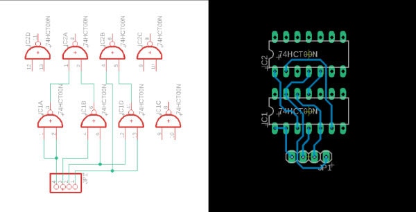
Normally, logic gates come in IC packages that combine multiple gates on a single IC. The gates in an IC are usually equivalent regarding their timing and functionality. Therefore, it doesn’t matter which of the gates you use, which can help you reduce the number of crossing traces in a finished PCB design. Doing so can also make your life easier when placing components and routing traces. Consider the following example:
 This example shows the first schematic and PCB design approach. Note that you could make this a single-sided design, but the traces would quickly become very long, and they would clutter up the rest of the PCB.
Just by using different gates, the PCB layout becomes much cleaner and only uses the bottom side of the board:
 In this second example, I swapped some of the logic gates. The inputs and output pins are closer together. Thus, the resulting PCB design is easier to route using only the bottom side.
Summary
This article took a quick look at a few common mistakes when designing digital circuits. You have to pay attention to a few things when working with digital electronics. Some more powerful integrated circuits need smoothing capacitors close to their power pins. Adding these external components ensures that the circuitry reliably works as intended. Next, make sure to use an accurate clock signal in your entire design. Also, check whether the clock frequency meets the requirements of all the components in your design. Lastly, avoid mixing devices that use different voltages in the same build. While it is possible to do so, adding ICs that require different voltages to operate can cause issues along the way.
Have questions or comments? Continue the conversation on TechForum, DigiKey's online community and technical resource.


