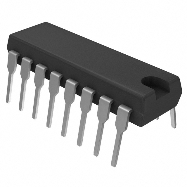
制造商零件编号 1140-272K-RC
FIXED IND 2.7MH 2.2A 555 MOHM TH
Bourns Inc.
License: Apache License, Version 2.0 Power Supplies Arduino ARM mbed
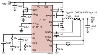
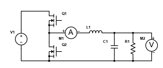
Now that we’ve designed the circuit and its passive components, we can select some components off Digikey! As a reminder, here’s the circuit we’re designing, a synchronous buck converter implemented using MOSFETs.
Passive Component Selection:
From the equations explained in the last article, the inductor L= 2.7mH and the output capacitor C=15.2μF. Given these component values, we can now pick out some components off DigiKey!
First the inductor. We’re looking for a fixed inductor of about 2.7mH, rated for at least 2A to give us some safety margin. Filtering for inductors that are in stock, at least 2.5mH, rated for at least 2A, and with through-hole termination so we can actually mount it without designing a PCB, a 2.7mH inductor from Bourns Inc looks like it will work. I’ll add it to my design in Scheme-It, so I can get a BOM (bill of materials) going for this project.
Now we can pick the output capacitor. We’ll want an aluminum electrolytic capacitor for this application; the electrolytic capacitors will be rated for ripple currents and the appropriate voltage and temperature, while other types of capacitors may not be as suitable, despite having the necessary capacitance. We’ll want a capacitor rated for at least 25V; this gives some headroom above the maximum input voltage of 17V. Our ripple current is 0.05A at 10kHz, so we’ll want to filter out capacitors that can’t handle at least twice as much at the proper frequency (100mA at 10kHz), again giving us some margin. Again, we’ll want a through hole device, so we don’t have to design a PCB.
The Kemet ESY156M035AC2AA is a 15 μF capacitor rated for 35V. It can take 190mA of ripple current at 100kHz, and 133mA at 120Hz, so it should be more than adequate for our 50mA at 10kHz. This capacitor also gives us its ESR (equivalent series resistance), which can help us make our model more accurate. We’ll add this resistance in series with the output capacitor, and see how it affects the operation of the converter in simulation. I’ll also add it to Scheme-IT, to keep the BOM up to date.
We don’t have to pick out the resistor- remember, it was a stand in for the current draw of the microcontroller!
Implementing the Ideal Single Pole Double Throw Switch:
We do have to pick out the MOSFETs we’ll use to implement the switch shown in the ideal schematic of the buck converter. Unfortunately, there aren’t single pole double throw (SPDT) switches available that are suitable for this application. These switches are typically relays or hand operated switches, which you aren’t going to be able to switch the 10,000 times per second we need for this application. We instead have to use single pole single throw switches, which are either open or closed.
Transistors, which we can switch at the required speed, can be used to implement single pole single throw (SPST) switches in a way that achieves the same topology altering effect as the SPDT. Classically, the buck converter is implemented with a transistor (usually an IGBT+diode or MOSFET) on the high side and a diode on the low side. The duty cycle tells you how much of the period the transistor switch is closed; the diode conducts, and the transistor is open for the rest of the period.
We’re going to do a slightly different design: a synchronous buck converter, which uses MOSFETS or IGBTs for both switches, in a half-bridge configuration. In this configuration, duty cycle tells you how long the top switch is closed and the bottom switch is open. During the rest of the period the opposite is true: the top switch is open, and the bottom switch is closed, conducting when the diode would in a normal buck converter. The two devices run in “complimentary” operation; they’re never closed at the same time, as this would cause a short circuit that can destroy the devices.
A note on switching frequency and device technologies:
MOSFETs generally switch faster than IGBTs, especially when they’re made using Silicon Carbide (SiC) or Gallium Nitride (GaN) instead of just Silicon (Si). Higher switching frequencies have a number of advantages. In the equation used to specify the inductance, we see that the inductance is directly proportional to the switching period, so it’s inversely proportional to the switching frequency. The higher our switching frequency, the smaller our inductance can be for the same inductor current ripple. This lets us use smaller (read cheaper, lighter, & easier to package) magnetics components, reducing the cost and size of our converters. Faster switching frequencies also reduce switching losses, through mechanisms I’ll cover in another article. Reduced switching losses allow not only for more efficient converters, but also for smaller, cheaper converters, as switching losses create heat that must be removed using bulky fans or heatsinks. A higher switching frequency lets us design control loops with higher bandwidth; this lets us design converters that respond more quickly to load changes, as we’ll see in the section describing the control design for this buck converter.
Switching frequency is limited largely by device technology, which is in turn limited by cost; the faster you want to switch, the more you have to pay for a SiC or GaN device to replace cheap and ubiquitous Si devices. There exists an optimal design that minimizes cost of the devices, the magnetics, the cooling and the gate driving circuitry. Finding that optimal combination is a topic of active research, and is highly specific to the application of the converter. For this simple example, we’ll use a switching frequency of 10kHz, which is about as fast as we can reliably go in Silicon, the cheapest and most widely available device technology.
Selecting the Half-Bridge:
A half-bridge is just two transistors in series, with a tap to connect to the midpoint between them as well as the bus formed by the two series terminals. A buck converter implemented with a half-bridge is shown below. Duty cycle now is the fraction of the period that Q1 is on and Q2 is off.
Our half bridge has a few important requirements: it must be able to withstand more than the maximum input voltage (16.9V), ideally more than twice it, so 34V. It must be able to carry at least the rated current (0.5A), ideally more than twice it, or 1A. It must be able to switch at at least 10kHz; this is also a function of the gate drive we select for it. As far as the half-bridge module is concerned, this is a limit on the gate capacitance, which the gate driver will have to charge and then discharge very quickly to turn the devices on and then off again. MOSFETs are commonly specified in terms of the threshold voltage required to turn them on; this voltage is created by pumping current into the gate, charging the gate capacitance until this threshold voltage is reached. Gate drivers that can source and sink higher currents can charge and discharge the gate capacitance of a MOSFET faster, allowing for higher switching frequencies.
On Digikey we’ll filter the Single FETs, MOSFETs section to get something we like. Since this is a low power application, we’ll select two discrete MOSFETs to make our half-bridge. Two Alpha & Omega AOI4286 MOSFETs should work. These MOSFETs are rated for 100V drain source and up to 14A continuous through the drain. They can turn on and off in a total of 29ns, corresponding to a switching frequency above 34MHz; their switching performance is more than adequate for our 10kHz application, and our switching frequency is likely to be limited by the gate driver rather than the MOSFETs themselves. These MOSFETs can take up to ±20V gate to source, which will inform the selection of the gate driver. I’ll add two of these MOSFETs to the Scheme-It design.
Selecting the Gate Drivers:
Having selected the MOSFETs, we now need a gate drive to turn them on and off according to our control scheme. The MOSFETs require up to 10nC of gate charge to turn on when driven with 10V. Using Q=It, it can be calculated that a gate drive current of 100mA can drive the MOSFET at up to 5MHz, which would make turn on and turn off times of the transistors negligible for our 10kHz application.
Two Toshiba TLP351(F) optically isolated gate drivers will work. These are capable of outputting 2A, and operate off a supply ranging from 10-30V, allowing it to be powered from the rectified input voltage that serves the buck converter itself, with the help of a linear voltage regulator outputting 12V (DK part number MC7812CTGOS-ND). I’ll add two to the Scheme-It, along with the linear regulator to provide a nice, clean supply voltage for both the gate driver and any PWM circuitry we add.
Selecting the Pulse Width Modulators:
The TI TL594CN PWM IC should work- it will output a complimentary PWM signal with configurable dead-time to prevent shoot throughs. The circuit also contains integrated operational amplifiers, one of which we’ll use to implement average current mode control directly in the chip. An external op-amp will be required to implement voltage control, but this chip will both set the duty cycle and generate the pulses corresponding to it, which will go to the gate driver to drive the switches. Alternatively, the duty cycle could be fed directly to the feedback pin, which is connected to the input of the PWM comparator, allowing me to use this chip to generate PWM signals from an arbitrary input signal, potentially even from a digital controller’s DAC.
And with that, the buck converter circuit has been fully specified. In the next post, we’ll design the controls and implement them using analog op-amp circuits.