Designing a Project with Multiple Voltage Levels
2023-09-19 | By Zach Hipps
I have an Arduino board that runs on 5V logic and a temperature sensor module that runs on 3.3V logic. If you're new to electronics, you may have come across this situation and you weren't really sure what to do. In this article, I'm going to talk about what to do when your project needs more than one voltage level. This situation is really common. Some devices run off 5V, while others will run off of 3.3V or even 1.8V. When you go online and read about what to do, you find all sorts of information about voltage regulators, voltage dividers, and logic level shifters. With so much information out there, hopefully, this will help clarify some of that.
If I were to connect the 5V logic pins of this Arduino board to the 3.3V logic pins of the temperature sensor, it would probably damage the pins on the sensor. So as electronics makers, we need to figure out how to safely connect these two components. It's not just a problem feeding the 5V into the 3.3V part, it can be a problem going in the other direction as well because sometimes 3.3V isn't enough to trigger a logic HIGH in some 5V devices.

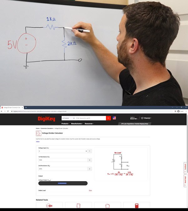
As you learn electronics, you’ll run into something called a voltage divider. It's a simple circuit that uses two resistors to reduce voltage. I've got a 5V supply that runs through a 1k resistor and then through a 2k resistor. If I take my multimeter and measure across the 2k resistor, I'll get a voltage level of 3.3V. You can test this out by building the circuit on a breadboard. If you want to learn more about voltage dividers, you can go to DigiKey has a really awesome voltage divider calculator.
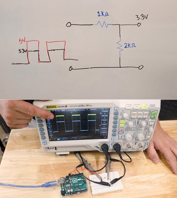
Let's say, instead of a constant 5V signal, you had a changing 5V signal, like a square wave from a clock signal. You could use a voltage divider to convert the 5V clock signal to a 3.3V clock signal. I have a 50Hz square wave coming from the Arduino board, and it's being sent through a voltage divider. The yellow signal trace on the o-scope is the 5V input and the light blue trace is the 3.3V output. So, if you had some sort of data signal or clock signal that was 5V, you could easily lower it down to 3.3V using a voltage divider like this.
At this point, you're probably thinking to yourself, great! If I need 3.3V, all I need to do is build a simple voltage divider and I can power all my 3.3V components from the voltage divider, but this is not a good idea, and I'll tell you why. You might be able to get away with this if your load is small, but any loads that you attach to the 3.3V output are going to need to dissipate their power through one of the resistors in the voltage divider. Anything more than just a small amount of current is going to dissipate a lot of heat through that resistor and could easily destroy it. So, that means that this is a really inefficient way to supply power to a component. In other words, voltage dividers are a great way to reduce the logic level of a signal, but they are not ideal for powering the component.
When powering a 3.3V component with a 5V supply, you’ll want to use some sort of voltage regulator. In this case, we're lucky because the Arduino board already has a 3.3V regulator, so we don't have to add our own. If you were using another board or in some other situation where you didn't have one, you would have to supply your own 3.3V regulator. I cover linear regulators as well as switch mode power supplies in another article, so go check that out if you want to learn more about voltage regulators.
At this point, I think I've covered all the pieces to safely connect the 5V Arduino board with the 3.3V temperature sensor module.
So, in the example from the beginning of the article, I could use a voltage regulator to supply the 3.3V to the temperature sensor module, then I could use a voltage divider to drop the 5V logic signals down to 3.3V allowing me to safely talk to the sensor. But what happens if I need the sensor to talk to the Arduino board? It has 3.3V signals, and the Arduino board is running on 5V logic! In this case, I’ll use something called a logic level shifter. This is a breakout board for a little chip that will do bi-directional logic level shifting. That means that it will go from 5V to 3.3V and the other way around. If you had a project that had a whole bunch of 3.3V components that needed to talk to a 5V microcontroller, this would be the perfect breakout board because there are eight channels on here. That means that you can connect eight signals that talk bi-directionally back and forth.
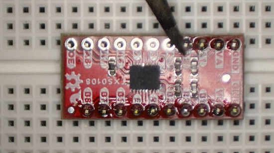
To demonstrate logic level shifting, I've got the temperature sensor hooked up through the level shifter to the Arduino. The sensor uses the SPI protocol, which is the “serial peripheral interface”, so it has four data lines. Chip select, data in, data out, and clock. Three of those four data signals are coming from the microcontroller into the sensor and so those will be shifted down to 3.3V. The data out signal coming from the sensor is going to go in the other direction, so it needs to be shifted up to 5V so that the microcontroller can read it.
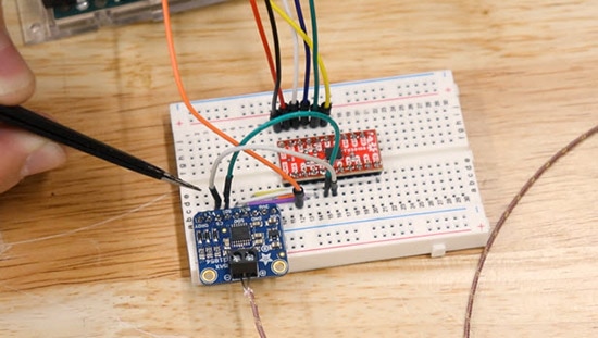
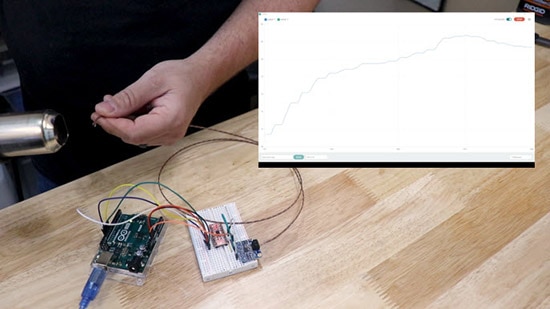
The long wire coming out of the sensor is the thermocouple. It can be put in really hot places to measure temperature. These are commonly found on 3D printers because they're a great way to measure really high temperatures. I've got an example sketch running on the Arduino board that just continuously prints out the temperature. I'm going to take a heat gun and heat up the tip of the thermocouple, and we'll see the results on the serial monitor. This is a really good demonstration because the SPI protocol has data running in both directions. So, there will be shifting in both directions. The cool thing about the Arduino IDE is that it has a serial plotter so we can visually watch this temperature change. It draws a graph and as the temperature rises, the line goes up and down. Once I take away the heat, we can watch it start cooling down.
When you have components in your project that use multiple voltages, it can be a little bit confusing for people beginning with electronics. Hopefully, this article and this demonstration cleared up this topic for you.
Recommended Reading

Have questions or comments? Continue the conversation on TechForum, DigiKey's online community and technical resource.
Visit TechForum




 中国
中国