Getting Started with High Precision Temperature Sensing using a MAX31865 and PT1000
2021-11-24 | By Maker.io Staff
Some high-precision applications, such as temperature sensing in lab equipment or monitoring a fabrication process, for example, require the use of a high-precision resistive temperature detector (RTD). This article gives an overview of RTDs in general and how you can get started with using the MAX31865 amplifier for high-precision temperature sensing applications.
Specifications and Things to Consider When using the MAX31865
An RTD is, simply put, a resistor that exhibits a strong correlation between its resistance and the temperature. Therefore, the resistance of an RTD changes when the temperature changes. You can measure this change in resistance to determine the temperature in the environment around the probe. A PT1000, for example, has a resistance of 1000 Ohms at 0°C. To make use of an RTD, you must use a high-precision amplifier that makes the small changes in resistance visible to digital electronics such as an Arduino.
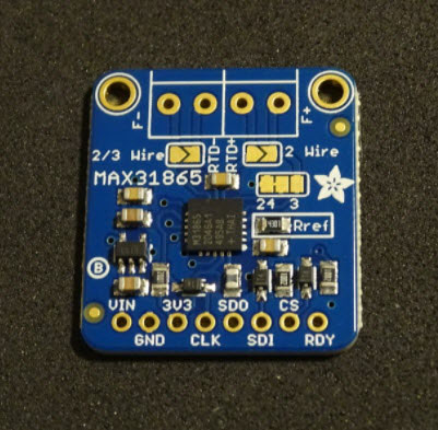
 The Adafruit MAX31865 breakout board is just about the size of a quarter-dollar coin. Image Source: https://learn.adafruit.com/assets/37318
One negative side-effect of RTDs is that the connected wires often already impact the resistance of the probe. Therefore, to accurately measure the temperature in the environment, you must use an amplifier that can handle small changes in resistance. The amplifier should, ideally, also compensate for the added resistance caused by the wires that connect the probe to the amplifier.
The Adafruit MAX31865 breakout board allows you to utilize a high-precision RTD amplifier in your custom microcontroller-based projects. The breakout board supports two, three, and four-wire RTDs, and it’s also 5V and 3.3V compliant. Please note that the board doesn’t come with an RTD probe. You can, however, buy a PT1000 such as this or use one that you already have. Note that you can also buy a PT100 version of this breakout board here.
Pinout and Hookup Guide
The MAX31865 breakout board contains eight I/O pins and four additional pins designed to take standard screw terminals. The four additional pins are where you need to connect your RTD probe:

You can group the eight I/O pins at the bottom edge of the breakout module into three categories. The first three pins allow you to supply the breakout board with 3V to 5V. The third pin, labeled 3V3, is connected to the breakout board’s 3.3V voltage regulator. The 3V3 output allows you to connect 3.3V devices without the need for an additional external voltage regulator.
The following four I/O pins are all required for SPI communication. Connect SCK on the breakout module to the SCK pin of your Arduino. Next, connect the SDO pin of the sensor board to MISO on the Arduino and SDI to MOSI. Then, attach the module’s CS pin to any unoccupied digital GPIO on the Arduino. You can also use any four digital I/O pins of the Arduino, as the module works well with software SPI.
Lastly, the RDY pin on the MAX31865 module signals your microcontroller when the sensor is ready to transmit the next temperature reading.
 This wiring diagram shows all the connections you need to make between an Arduino board and the MAX31865 breakout module. It doesn't include the PT1000 probe.
Connecting an RTD Probe
As previously mentioned, the two big screw terminal blocks are designed to take a single two, three, or four-wire RTD. By default, the breakout board is set up to expect a four-wire configuration. For all other types of RTDs, you’ll have to bridge some of the solder pads on the module.
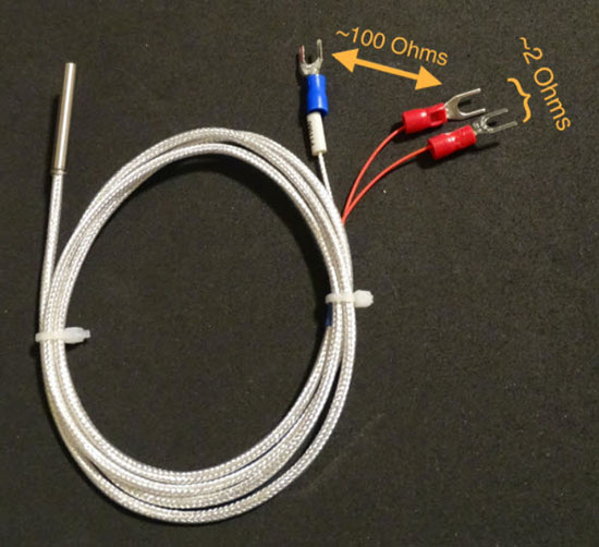
If you have a four or three-wire RTD, it is important to determine which pair of wires are connected internally. You can do this by using a multimeter. The connected ones will have a low resistance of around two ohms. The cables that aren’t directly connected will have a greater resistance of approximately 100 Ohms:

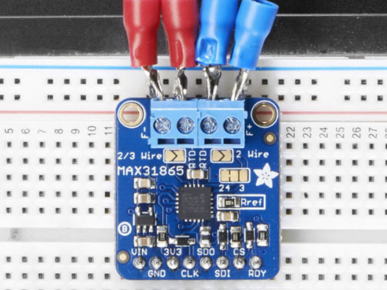
If you have a four-wire RTD, you only need to connect each pair of wires to either one of the screw terminals. It doesn’t matter which pair of wires goes to what screw terminal, and there’s no need to change any jumper settings:
 Connect each pair of wires to one of the screw terminals. You don't need to change any jumper settings when using a four-wire RTD. Image Source: https://learn.adafruit.com/assets/37299
If you’d like to use a three-wire RTD, use the three rightmost contacts of the two screw terminals. In three-wire RTDs, two of the wires are connected internally. Use a multimeter to determine which two are connected. Often, those two wires share the same color. Plug those two wires into the two rightmost terminals (the order doesn’t matter). Then, plug the third wire into the third terminal position from the right.
Next, you must cut the thin trace between the two-way jumper that sits below the right screw terminal. Then, solder shut the two rightmost pads of the said jumper. Additionally, you should use a small blob of solder to bridge the contacts of another jumper below the left screw terminal:

For two-wire sensors, plug one wire into the left screw terminal and then connect the other wire to either one of the right terminal’s contacts. Lastly, put a blob of solder on both jumpers right below the screw terminals:

How to Determine the Temperature Using an Arduino
To get started with using the MAX31865 with an Arduino, make sure that you first download the Adafruit MAX31865 library using the Arduino IDE’s built-in library manager. Then, you should be able to compile and upload the following short test program:
#include <Adafruit_MAX31865.h>

// The value of the Rref resistor.
// Use 430.0 for PT100 and 4300.0 for PT1000
#define RREF 430.0
// The nominal 0-degrees-C resistance of the sensor
// 100.0 for PT100, 1000.0 for PT1000
#define RNOMINAL 100.0

// The constructor expects the Arduino pin-numbers
// in the following order: CS, DI, DO, CLK
Adafruit_MAX31865 sensor = Adafruit_MAX31865(10, 11, 12, 13);
unsigned long lastRead = 0UL;

void setup()
{
  Serial.begin(9600);
  // use 2WIRE, 3WIRE, or 4WIRE as necessary
  sensor.begin(MAX31865_3WIRE);
}


void loop()
{
  // Read the temperature once every second
  if(millis() - lastRead > 1000)
  {
	uint16_t rtd_value = sensor.readRTD();
	float ratio = (float)rtd_value / 32768.0f;

	Serial.print("RTD Resistance: ");
	Serial.println(RREF * ratio, 8);

	Serial.print("Temperature:	");
	Serial.println(sensor.temperature(RNOMINAL, RREF));

	lastRead = millis();
  }
}
In this short sketch, the setup method initializes the serial console and the sensor object. The loop method then requests the resistance and the temperature from the MAX3816 once every second. The sketch then prints those values to the serial console:
 This shows the serial output of the sketch from above. Notice how the resistance changes as the sensor's temperature increases while I held it in my hand.
Summary
Resistive temperature detectors, or RTDs, are perfect for all applications that require high-accuracy temperature sensing. Those applications can range from 3D printing to high-precision lab equipment. The resistance of an RTD correlates to the temperature of the environment. Therefore, you can determine the temperature by measuring the probe’s resistance. You’ll need a high-precision amplifier to accomplish this. The MAX31865 is such an amplifier, and the Adafruit MAX31865 breakout board makes it accessible to makers.
This breakout board supports two, three, and four-wire RTDs, and you can configure which type the device should expect by soldering shut certain jumpers on the board. Using the MAX31865 breakout with an Arduino is an easy task. You only need to connect the standard SPI and power wires. The Arduino library, which you can download using the Arduino IDE’s built-in library manager, supports software and hardware SPI. The short example code uses software SPI to request the current temperature from the sensor once every second. The sketch then outputs the resistance and the temperature to the serial console.

Have questions or comments? Continue the conversation on TechForum, DigiKey's online community and technical resource.
Visit TechForum


 中国
中国