制造商零件编号 LM2678T-5.0/NOPB
IC REG BUCK 5V 5A TO220-7
Texas Instruments
There are a lot of ways to power your project. In fact, previously I wrote a whole post about this topic. In that post, I touched briefly on switch mode power supplies, but I didn't get the chance to dive deeply into that topic. So, in this blog post, I'm going to talk about buck converters, which are a type of switch-mode power supply. Unlike linear regulators that shed their excess voltage as heat, buck converters switch their supply voltage on and off very quickly to adjust their output voltage. They typically use a feedback circuit to vary the duty cycle of that switching to adjust the output voltage. With buck converters, you can take a wide range of input voltages and regulate them down to a fixed output voltage in a really efficient way. The details of this process are really interesting and informative, so let's dive in!

Let's say I have a 36V source voltage and I need to power a 12V load. I can add a switch in series with the load. When the switch is closed, however, the load is going to receive the full 36V, which I don’t want. But if I open and close that switch repeatedly, the average voltage that the load receives will be less than 36V. Let's say, for example, I closed the switch for one second and then I opened it for 2 seconds. In other words, the switch is closed one-third of the time. This means on average; my load will receive 1/3 of the input voltage. In this case, which would be 12V. Unfortunately, I can't leave my circuit like this because when the switch is open, no current can flow to the load.

So, what if I add a capacitor in parallel with the load? This way when the switch is closed, the capacitor is slowly charged up. And when the switch opens, the capacitor will provide a voltage to my load. The capacitor will do a good job of opposing that quick change in voltage, but to complete the low pass filter, I really need to add an inductor in series. The opening and closing of the switch create a square wave. The inductor will oppose those quick changes in current and the capacitor will oppose the quick changes in voltage. The low-pass filter turns the square wave into something more of a constant DC voltage.

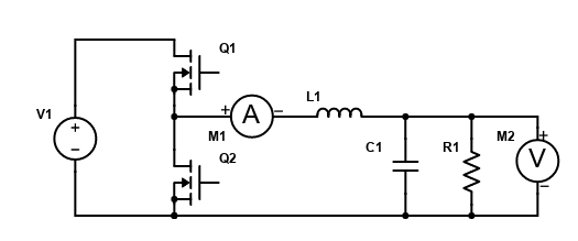
However, there's still a big problem with this circuit. I would have to open and close the switch really fast in order for the low-pass filter to be effective. Not to mention my finger would get really tired of opening and closing that switch. So, I'm going to replace the switch with a MOSFET. The MOSFET can be controlled using a microcontroller, a 555 timer, or some other component. When the MOSFET is closed, current will flow through the inductor and capacitor. Both of these components will store energy in their magnetic and electric fields, respectively.

Here's where this circuit presents another problem. Once the inductor has energy stored in its magnetic field and the MOSFET opens, that energy has nowhere to go. This built-up energy creates a huge reverse voltage spike. The current will want to flow back through the MOSFET, which will destroy it. Fortunately, the solution is pretty simple. I can just add a diode into the circuit, which provides a path for the current to flow when the MOSFET is open. I can adjust the amount of time the MOSFET is closed versus open (this is also called the “duty cycle”) in order to adjust the output voltage.


To make this a closed-loop system, whatever is controlling the duty cycle of the MOSFET needs to know what the output voltage is. Let's say I'm using a microcontroller. I can use a feedback loop to determine what the duty cycle needs to be in order to get a specific output voltage. By using a buck converter instead of a linear regulator, I can get efficiencies upwards of 80% or 90% as opposed to like 30% or 40% of a linear regulator.

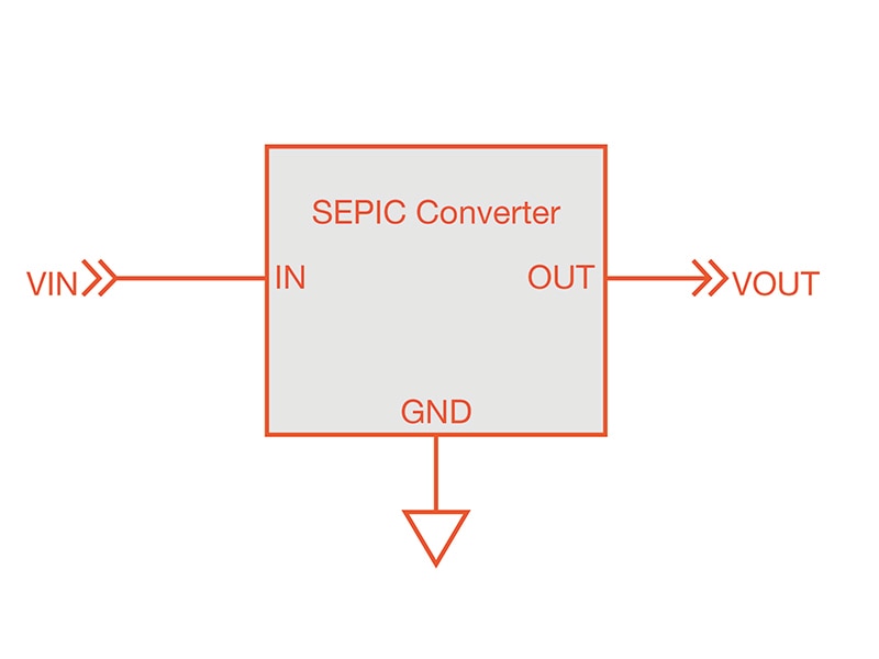
This buck converter design is called an asynchronous buck converter because it uses a diode to conduct electricity when the MOSFET is off. If I want to improve efficiency even further, I could replace the diode with another MOSFET, making it a synchronous buck converter. The synchronous buck converter has many advantages over the asynchronous topology.

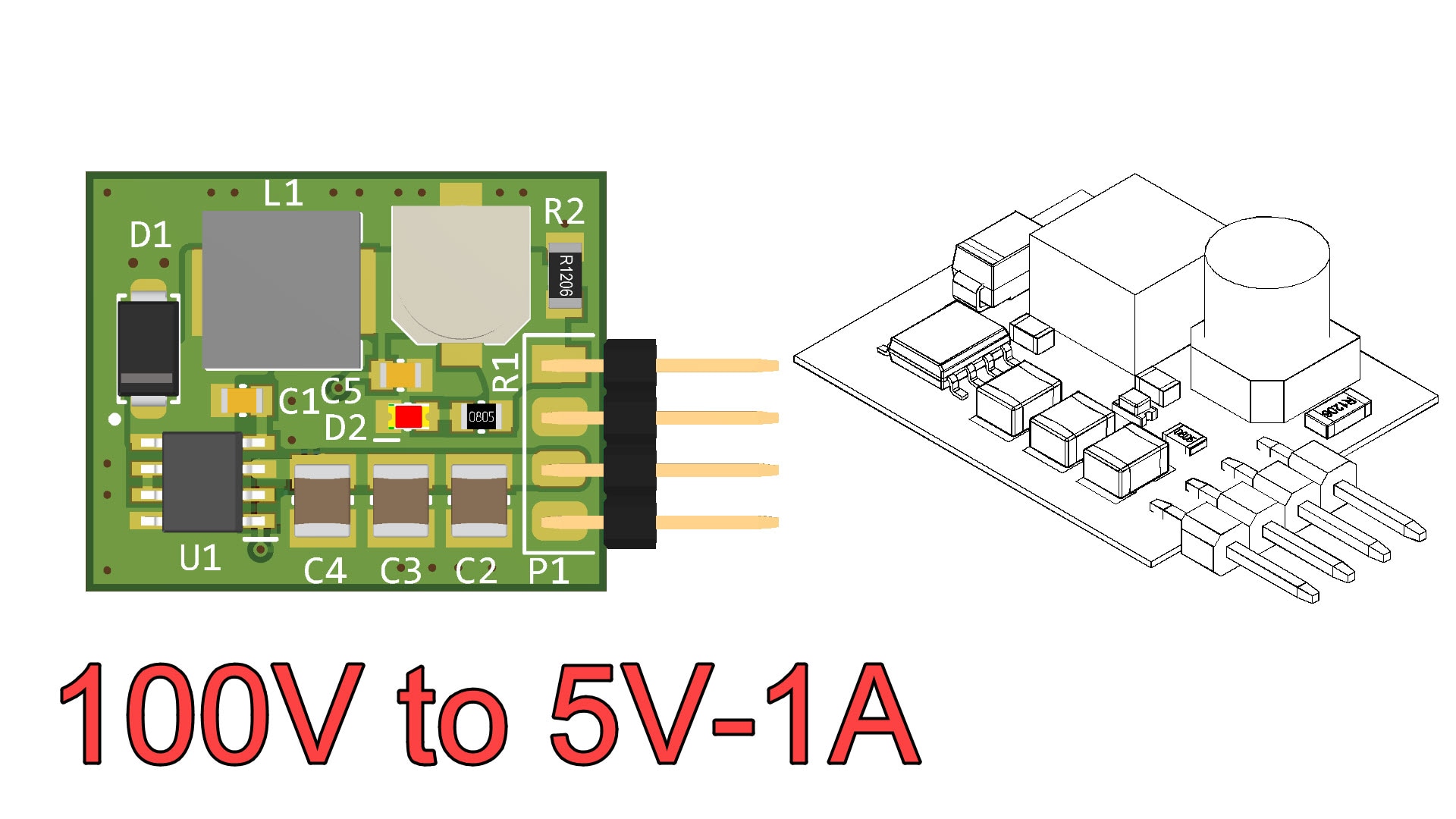
It may seem like this is a lot of work to include in your circuit, but the reality is that chip manufacturers have already done all of the hard work. If you go on the DigiKey website and search for buck converters, you'll find hundreds of chips that are ready to use with just one or two additional components. In fact, I designed a circuit board that uses an LM2678 buck converter. It takes an input voltage from 8V up to 40V, and it will output a fixed voltage. You can also get the version of the chip that has an adjustable output voltage. Hopefully, this blog post helped you understand buck converters just a little bit more, and got you excited about including them in your next project!