Tank Circuits: The Operation and Application of an LC Circuit
2025-01-06 | By Don Wilcher
A tank circuit, consisting of an inductor (L) and a capacitor (C) wired in parallel or series is part of electronic circuit fundamentals. Another name used to describe a tank circuit is a resonant circuit. A tank circuit is particularly useful in the design of power supplies, filters, oscillators, and radios. A resonant frequency is established by the tank circuit which is used to remove unwanted noise (filters), provide appropriate audible tones and signals (oscillators), and allow frequency-selective networks (radios) to be selected. In radio, a tank circuit known as a tuned circuit is used in creating a frequency-selective network. A tank circuit exhibits a resonant frequency where it can efficiently transfer power and selectively filter signals, making them critical in both communication and power systems. Understanding the operation of a tank circuit is important in the field of electronics for optimizing performance and achieving maximum power transfer at resonance in power supply and communication devices.
 A Tuned LC Circuit image source Wikipedia.
What is a Tank Circuit?
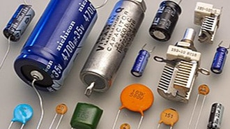
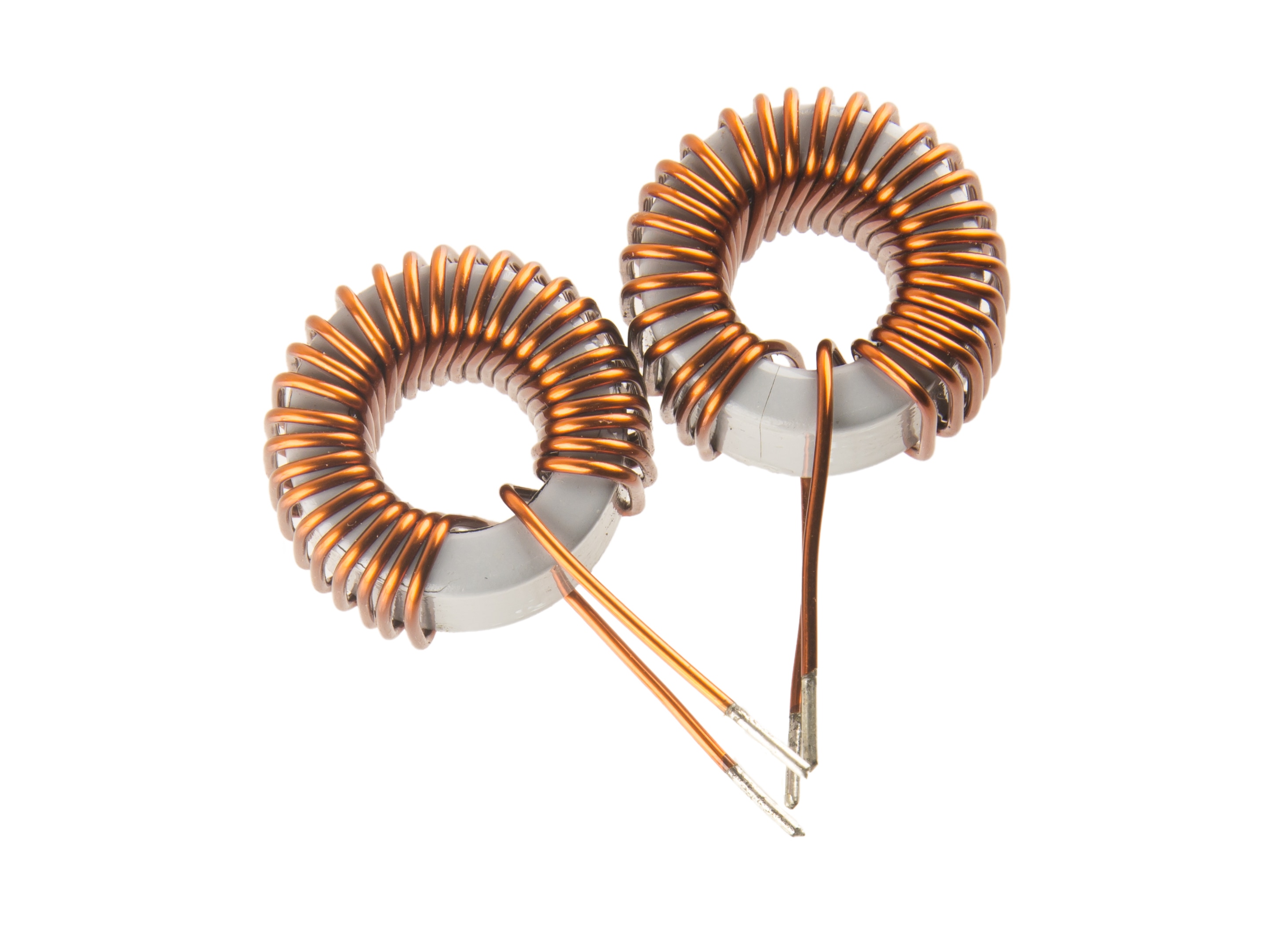
An LC circuit also known as a tank circuit or resonant circuit uses two passive components, an inductor (L) and a capacitor (C). The electronic device is called a tank circuit based on the inductor and capacitor being able to store electrical energy. This energy storage ability is similar to a tank capable of storing water. The electrical energy consists of electrical current and voltage that switches between the two energy storage components. The electrical current produces a magnetic field based on the inductor’s windings and the electric field stored by the capacitor. The changing magnetic field of the inductor induces an electric field that is stored between the plates of the capacitor.
How a Tank Circuit Works?
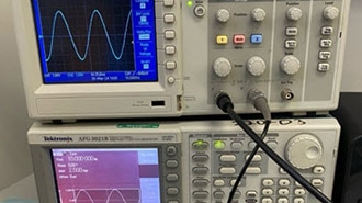
A tank circuit's two key electronic components are the inductor and the capacitor. The switching magnetic field and the induced electric field produced by the inductor and stored by the capacitor oscillate at a specific frequency. An applied alternating voltage initially starts the oscillations. The switching magnetic field and the electric field are continuous so long as the applied alternating voltage keeps the circuit active. Removal of the applied alternating voltage will stop oscillations occurring in the tank circuit. A tank circuit can be wired in a series or parallel configuration.
 A solderless breadboard wired series Tank Circuit.
The capacitor stores energy as an electric field in its plates. Opposite charges of the electric field are stored between the capacitor’s plates. A magnetic field is produced when electrical current flows through the inductor. As the exchange of electrical energy between the capacitor and inductor exists, the oscillations will be sustained. The sustained oscillations will produce a specific resonant frequency. This resonant frequency is based on the values of the inductor and the capacitor. The resonant frequency can be determined using a basic equation. The resonant frequency is the natural oscillations produced by the tank circuit inductor and capacitor components.
 Resonant Frequency equation
Understanding Resonant Frequency
In the field of electronics, resonant frequency is an important electrical parameter for the tank circuit. The resonant frequency equation is predicated on the inductor and capacitor values used in the tank circuit. The fo is the resonant frequency variable. The resonant frequency is represented by the unit of hertz. The resonant frequency is important in electronics due to the different alternating input frequencies (voltage signals) applied to it. At a specific frequency, the sustained switching energy is efficient, thereby providing a maximum amplitude or power oscillation. Therefore, tank circuits are designed to resonate at desired frequencies for the intended application.
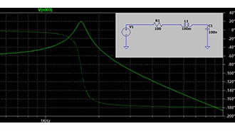
 A tank circuit resonant frequency plot.
Types of Tank Circuits
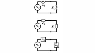
A tank circuit can be wired in series or parallel. In a series tank circuit, the inductor and the capacitor are connected in series. In this circuit arrangement, the inductor and the capacitor have the same electrical current flowing through them. The impedance in a series tank circuit is low at the resonant frequency. With low impedance, maximum current flows through the circuit. Maximum power occurs in a series tank circuit due to the increased electrical current flow provided during resonance.
In a parallel tank circuit, the inductor and capacitor are wired in parallel. High impedance is created in a parallel tank circuit primarily established by the capacitor. With high impedance, the tank circuit may be used as a filter effectively blocking or rejecting unwanted signals or electrical noise at designated frequencies. Radio receiver circuits benefit from a parallel circuit due to the passing of signals at designated frequencies.
 Tank Circuit configurations: (a) Series, (b) Parallel.
Applications of Tank Circuits
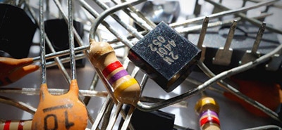
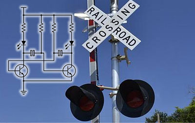
Practical applications arise from the tank circuit's ability to resonate at specific frequencies. One practical application of tank circuits is radio transmitters and receivers. Tank circuits play an integral role in the selective tuning of radio station frequencies. With the adjustment of the inductor and capacitor, the tank circuit can be adjusted precisely to resonate at the desired frequency being transmitted by a radio station transmitter. With such selectivity of the receiver, radio stations can be heard through the loudspeaker. Therefore, the tank circuit is tuned to the desired radio frequency using the parallel LC circuit configuration. Another application of tank circuits is in oscillators. Oscillators generate periodic signals used for timing applications, signal generation, and clock circuits found in analog and digital devices.
 A radio Printed Circuit Board (PCB). Image source Corporal Radio Restoration
Filtering Applications
Besides radio receivers and oscillators, tank circuits play an important role in filtering electrical noise in audio and wireless frequency signals. Tank circuits are designed to function as bandpass or notch filters. Allowing signals with a designated frequency to pass is the operation of a bandpass filter. Signals with frequencies outside the range of the resonant frequency are blocked by the bandpass filter. Notch filters are selective in blocking frequencies. Signals are blocked by the notch filter based on specific unwanted frequencies while allowing desired frequencies to pass. Audio equipment, communication devices, and instrumentation depend on signal clarity. Without signal clarity, the function and quality of these devices will be ineffective for the required designed application. These specific filtering applications and devices illustrate the importance of tank circuits used in modern electronics.
 An example Bandpass filter frequency response curve. Image source Spectra.com.
Conclusion
The tank circuit plays a crucial role in applications that depend on specific frequency performance. With an understanding of the basic principles of resonant frequency and the electrical behavior of inductors and capacitors, effective signal power operation and performance can be used in a variety of modern electronic products. The tank circuit’s oscillation feature allows radios to receive wanted stations, stable clock signals to be generated or remove unwanted noise from sensitive electronics using a clean and efficient method.