制造商零件编号 CFR-25JB-52-3K3
RES 3.3K OHM 5% 1/4W AXIAL
YAGEO
Breadboards Capacitors Resistors
Low and high-pass filters are used widely in the electrical engineering world. For example, these low and high-pass filters can be used in audio processing, image processing, communication systems, and sometimes biomedical signal processing. These filters do as their name suggests. They can filter out either a high frequency and let low frequencies pass, and they can do the opposite, filter out low frequencies and let high frequencies pass. In this blog, I am going to find the waveforms of the given high-pass and low-pass filter circuits for the components I am using. Upon building the circuit, I am going to compare the waveforms of the signal from the frequency to the waveform from the circuit components and see if they are the same or out of phase. I am going to use a function generator as well as an oscilloscope to measure these waveforms.
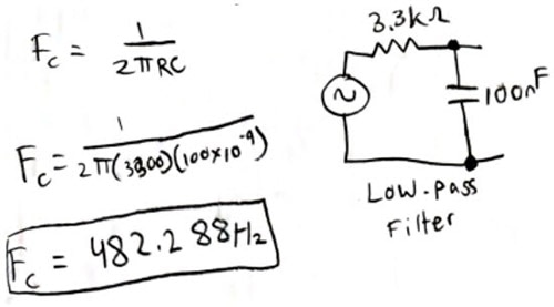
Low and high-pass filters, as discussed before, either filter out frequencies lower than the cut-off frequency or higher than the cut-off frequency. This cut-off frequency is determined by the equation listed below, where R is the resistance of the resistor, C is the capacitance of the capacitor, and 2π is a constant. This cut-off frequency and the order of the components determine how the circuit will respond to a given input frequency. A low-pass filter has the resistor first and then the capacitor second. Rather, the high-pass filter has the capacitor and then the resistor. If the input frequency is greater than the cut-off frequency and it is a high-pass filter, then the waveform will pass through unfiltered. If the input frequency is less than the cut-off frequency, then the waveform will be filtered and be out of phase and have a lower amplitude compared to the input waveform. The opposite is true when it comes to low-pass filters.
As stated above, the cut-off frequency is the frequency in which the low or high-pass filter filters out the frequency, which is calculated in the equation: 12RC. As stated above, R is the resistance of your component and C is the capacitance of your component. All that is needed for a high-pass filter is one capacitor, one resistor, and of course some jumper wires and a power supply. For this project, I used a 3.3k resistor and a 100 nano farad capacitor. For low and high-pass filters, you can really use any component values you want to. I used these specific components for ease of use and to get nicer values for a cut-off frequency. As shown below, I put my values in the given equation and came up with a cut-off frequency of 482.288Hz. This is the frequency in which the circuit will balance between to make the high and low-pass filters.
You can also use DigiKey’s Low Pass/High Pass Filter Calculator to find these values.


Here, I used a circuit simulation software called Multisim. With this, I was able to confirm my hand calculations by seeing that the higher frequency was indeed cut off after it reached the cut-off frequency of 482.288Hz. The graph shows that the amplitude is high in the lower frequency region, but as it crosses 482Hz, it starts to taper off and go in a negative direction. With the resistor first in order, in series with the capacitor, this creates the low-pass filter. The power source that is connected to it is a function generator, giving off a pulse that allows the waves to be seen on the oscilloscope. You can also do this with the high pass filter.

In the picture above, the low-pass filter circuit is built on the breadboard. The waveform is applied first through the resistor and then through the capacitor. The input frequency applied is less than the cut-off frequency, thus the filtered waveform is in phase and has no difference in amplitude compared to the input waveform. According to my understanding of low-pass filters and comparing this to my hand calculations, this makes sense.

Again, the low-pass filter circuit is pictured above. This time, the input frequency applied is more than the cut-off frequency, thus the filtered waveform isn't in phase and there is a difference in amplitude compared to the input waveform. For reference, the blue waveform (the applied waveform) is at 2 volts per division and the yellow waveform (the filtered signal) is at 1 volt per division. According to my understanding of low-pass filters and comparing this to my hand calculations, this makes sense.

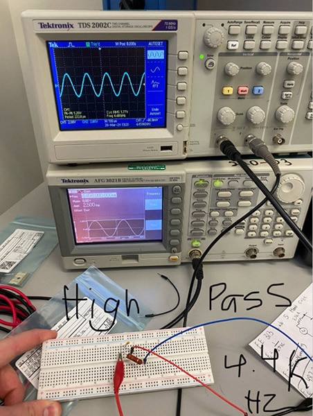
In the picture above, the high-pass filter circuit is built on the breadboard. The waveform is applied first through the capacitor and then through the resistor. This is the opposite of the low-pass filter. The input frequency is more than the cut-off frequency; thus, it will be in phase and has no difference in amplitude compared to the input waveform. According to my understanding of high-pass filters and comparing this to my hand calculations, this makes sense.

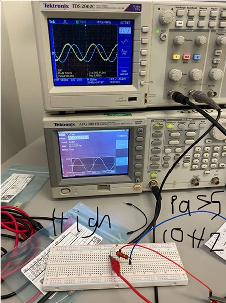
Again, the high-pass filter circuit is pictured above. This time the input frequency applied is less than the cut-off frequency, thus the filtered waveform isn't in phase and there is a difference in amplitude compared to the input waveform. For reference, the blue waveform (the applied waveform) is at 2 volts per division and the yellow waveform (the filtered signal) is at 50 millivolts per division. According to my understanding of low-pass filters and comparing this to my hand calculations, this makes sense.
When doing the simulation and real experiments, I got very similar waveforms and they compared and matched what they should be. The low-pass filter, in which the cut-off was 482 Hz, allowed a 10 Hz frequency to go through, but not a 1K Hz to go through, which is what I was expecting. The high-pass filter had the expected outcome as well, with the high frequency waves lining up, and the lower ones not getting passed through.
In conclusion, I was able to get a better understanding of how low-pass and high-pass filters work, as well as how the frequency cut-off works with the given components. I was also able to clearly see the similarities and differences between the waveforms when the components were flipped around. You can make a high or low-pass filter with any combination of resistor and capacitor and can figure out the cut-off frequency the circuit will have using the equation I have provided. This can be a fun little project anyone can do with a few supplies and is a good little learning experience to anyone wanting to know more about frequencies in electronics.