What Is an Eye Diagram in Electronics, And What Is It Used For?
2024-04-10 | By Mario De Lorenzo
Introduction
In the world of electronics, there are a plethora of tools and techniques that engineers and hobbyists use to analyze and evaluate the performance of digital communication systems. One of the most vital and widely used tools in this realm is the "Eye Diagram." Whether you're a seasoned professional or a budding electronics enthusiast, understanding what an eye diagram is and how to interpret it can be incredibly beneficial. In this blog post, we'll demystify the concept of eye diagrams, exploring what they are and their applications in the field of electronics.
What is an Eye Diagram?
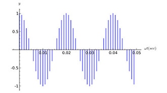
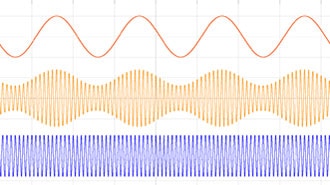
An eye diagram is a graphical representation of a digital signal's quality and integrity, particularly in the context of high-speed data transmission and reception. The name "eye diagram" comes from the distinctive shape of the graph, which resembles the shape of an eye. This graph is created by overlaying multiple signal periods on top of each other, forming a pattern that provides valuable insights into signal quality.
- Key Elements of an Eye Diagram:
- Vertical Axis (Voltage): The vertical axis of an eye diagram represents voltage or signal amplitude. It shows how the signal transitions between different voltage levels.
- Horizontal Axis (Time): The horizontal axis represents time. It is divided into two halves, with one half representing one bit period and the other half representing the subsequent bit period.
- The "Eye": The central and most critical part of the eye diagram is the "eye" itself, formed by the opening between the upper and lower signal traces. The width and height of this eye opening are key indicators of signal quality.

What is it Used For?
Eye diagrams are an indispensable tool for evaluating the quality of digital communication systems, and they serve several important purposes:
- Signal Integrity Assessment: Eye diagrams help in assessing signal integrity by providing information on issues like jitter, noise, and inter-symbol interference. Engineers can quickly spot irregularities, ensuring that the signal meets the required standards.
- Bit Error Rate (BER) Estimation: Engineers can estimate the bit error rate by counting the number of transitions that cross the eye's boundary. A wider and more open eye indicates lower error rates, while a narrower and more closed eye suggests a higher error rate.
- Equalization and Optimization: Eye diagrams assist in optimizing the performance of communication systems. Engineers can make adjustments to the system, such as equalization and filtering, to improve the eye opening and minimize signal degradation.
- Troubleshooting: When issues arise in a communication system, eye diagrams provide a visual representation of the problem. By observing the eye opening, engineers can identify the root causes of signal degradation and work towards solutions.
- Compliance Testing: In industries with strict standards and regulations, eye diagrams are used for compliance testing. They help ensure that a communication system complies with industry standards and can reliably transmit and receive data.
To plot an eye diagram and make effective use of it, you'll need certain equipment and tools. Below is a list of the general equipment and applications for eye diagrams:
Equipment Required for Plotting an Eye Diagram:
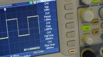
- Oscilloscope: A high-quality digital oscilloscope is a fundamental tool for generating and displaying eye diagrams. The oscilloscope should have sufficient bandwidth and sample rate to capture high-frequency signals accurately. Many modern oscilloscopes come with built-in eye diagram analysis features, simplifying the process.
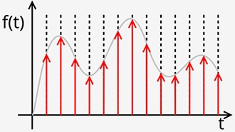
- Signal Source: You'll need a clean and stable signal source that generates the digital signal you want to analyze. This source can be a function generator, a bit pattern generator, or the actual transmitter in the system under test.
- Probes: Appropriate probes or accessories are necessary to connect the oscilloscope to the signal source. Differential probes are often used to accurately measure differential signals without introducing noise.
- Triggering Mechanism: To capture the data correctly, you need a triggering mechanism on your oscilloscope. This ensures that the signal is sampled at the correct point within each bit period.
- Clock Recovery Unit (Optional): In cases where the clock is not available along with the data signal, a clock recovery unit may be required to synchronize the oscilloscope to the data signal.
Conclusion
Eye diagrams are a powerful tool in the field of electronics, offering invaluable insights into the quality and integrity of digital signals in communication systems. Whether you're an amateur looking to expand your knowledge or a seasoned professional seeking to troubleshoot complex issues, understanding how to interpret eye diagrams is an essential skill. By leveraging the information provided by eye diagrams, engineers can design, optimize, and troubleshoot communication systems with greater precision and efficiency.