What is the I2S Communication Protocol?
2023-08-30 | By Maker.io Staff
Most, if not all, seasoned makers and hobbyists will have heard about I2C — a highly popular standard for transmitting data between microcontrollers and other similar devices. However, I2C and the more unfamiliar I2S protocol do not have anything in common other than their similarity in names. This article explores the unconventional, yet straightforward I2S communication protocol, its uses, and how it functions.
A High-Level Overview of I2S
I2S is a synchronous, serial communication protocol for exchanging digital audio data between sound-processing devices such as microcontrollers, audio codecs, or digital signal processors. It uses a shared clock signal to synchronize the data transmission between devices and transmits audio in a serial fashion. The protocol is often used in designs that require high-quality audio transmission.
On the physical level, the protocol requires three connections between the devices on a bus: the clock signal (SCK) for synchronizing communication partners, a word select (WS) line for switching between the left and right audio channels, and a dedicated data wire exclusively for transmitting audio information bit-by-bit.
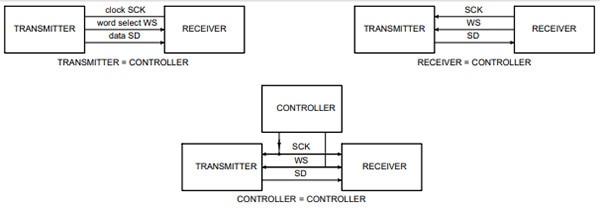 This diagram outlines three possible controller/device configurations commonly used with I2S. Note that there must always be exactly one controller generating the SCK and WS signals, and all other communication partners act as simple devices. Image source: NXP datasheet: https://www.nxp.com/docs/en/user-manual/UM11732.pdf
The protocol utilizes a controller/device (formerly known as master/slave) architecture. In simple systems, one IC acts as the single controller and the remaining are devices. In this scenario, the controller is responsible for generating the shared SCK and WS signals, and the controller is the only transmitter that can exclusively place bits on the data line. However, more complex systems may use an external controller to ensure that multiple transmitters and receivers can transmit bits via the data line. In this case, all senders and receivers act as devices.
Transmitting Audio Data in I2S
The protocol’s physical simplicity directly translates to its data format. In contrast to other protocols relying on intricate bit sequences to match particular patterns for the recipients to understand the message, I2S doesn’t rely on this approach. Instead, the clock signal continuously runs, and the bits representing the audio data are also placed continuously on the single data line. The transmission does not occur in frames of fixed sizes. Rather, the active transmitter sends any data available for transmission, while the receiver reads as many bits as possible — or as expected to be received. The only limitation is that the sender must transmit the data with the MSB first. Apart from this, the recipients and senders do not require agreement on fixed message lengths. Anything a receiver can’t process will be lost, hence why sending the MSB first is the sole requirement.
The sender can additionally clock out data bits on either the falling or rising edge of the SCK signal, but the receivers must read the data on the signal’s rising edge. Finally, there are no unused clock transitions. Each transition represents the transfer of one bit, regardless of whether or not there’s data on the bus. As a result, the MSB of the next word immediately follows the LSB of the last word without any padding or delays.
 This image shows an example data transmission of two frames consisting of three bits each. The data gets clocked out on the rising edge of SCK. Finally, note how the WS transition happens one clock cycle before frame 2 begins.
As mentioned, the WS channel can be used to signal that the data being transmitted is part of the left (WS is low) or right (WS is high) audio channel. Any transitions of WS must occur one clock period before the completion of a data frame.
Following this flexibility, the protocol doesn’t specify or limit the clock frequency.
The Bottom Line
I2S is a relatively less familiar communication protocol in the DIY space. However, the simple and efficient protocol definitions make it useful in a variety of applications, despite the protocol’s intended use for transmitting digital audio data.
The protocol utilizes a three-signal physical setup consisting of a synchronous clock, channel-select line, and data transmission wire. Furthermore, the protocol employs a controller/device architecture in which precisely one device is required to be the controller while the remaining act as peripherals. The controller device generates the clock and channel-select signals.
Data is sent out through the data line bit-by-bit, either on each falling or rising edge of the clock signal. However, the receivers must read data bits on the bus for every rising edge of the clock. The length of data frames is not limited, with the only limitation instead being that the sender must write the data beginning with the most-significant bit. Moreover, there are no wasted clock cycles, as each LSB of a message immediately precedes the MSB of the next word on the data bus.
Easily integrate I2S audio into your next project with our most popular development boards supporting I2S.


