There Are No Ideal Inductors
2015-08-26 | By Maker.io Staff
Figure 1: Real inductors
Image Source: http://en.wikipedia.org/wiki/Inductor#/media/File:Electronic_component_inductors.jpg
Ideal inductors
An inductor is a coil wire, often wound around a magnetic material such as powdered iron or ferrite. In my introductory circuits classes, I learned that inductors were lossless energy storage circuit elements that obey these current-voltage rules:
v=L di/dt
i=1/L ∫ vdt
In the real world, inductors only obey these simple rules under certain circumstances and are lossy. The actual inductance depends on biasing conditions and frequency.
There are no ideal inductors
If you ever touch an inductor on a high-current point-of-load converter, you may notice that it gets warm. This is because inductors are lossy in real life. Losses in inductors can be classified into two categories: conduction losses and core losses.
Conduction losses
Since an inductor is a wire coil, it will have resistive losses. The simplest of these to measure and calculate are the DC wire resistance. Conductors with a large cross-section (such as a low-gauge wire), will have lower resistance(R=ρ l/A, where R is resistance, ρ is the resistivity of the conductor, l is the length, and A is the cross-sectional area). The DC current losses are calculated using P=I^2 R, where P is power in watts, I is current, and R is the resistance of the wire.
There are frequency-dependent loss mechanisms as such. The skin effect describes how high-frequency currents induce eddy currents in a conductor, which in turn force high-frequency current to flow in the outer part of the conductor. This reduces the effective cross-sectional area of the conductor and increases the conductor’s resistance. To reduce skin effect–related losses, small wires can be wound in parallel around the core to provide a less resistive, more efficient inductor.
Another high-frequency loss mechanism is described by the proximity effect, which is that current in adjacent windings induces eddy currents that make the windings more resistant. Litz wire can be used to counter the proximity effect, but is expensive. Figure 2 is a plot of equivalent series resistance for some real inductors. Notice the increase in resistance that occurs after 1 MHz.
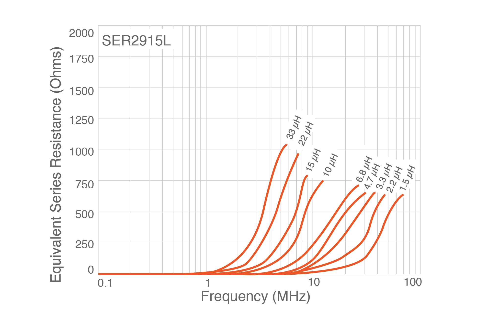
Figure 2: Current versus temperature derating
Image Source: http://www.coilcraft.com/pdfs/ser2900.pdf
Core losses
Voltage swings across an inductor cause losses in the core. It’s quite possible for an inductor to become very warm if enough voltage swings are placed across it, even if there is very little current flowing. If you are designing an inductor or a transformer, you should use a core material that will not be very lossy at a given line voltage and frequency.
Important datasheet parameters
An inductor datasheet will typically have two current ratings. One is the saturation current rating (ISAT), the other is the IRMS rating. The ISAT is the current at which the magnetic core begins to saturate, causing a reduction in inductance. During saturation, a reduction in inductance causes the current flowing in the inductor to increase without bound because the only thing limiting current flow will be the copper resistance and any source impedance in the power supply. When designing with inductors, ensure that you have plenty of margin between worst case inductor current and ISAT. Figure 3 is a plot of inductance versus current for some real inductors. Notice that inductance is relatively flat on the left side of the plot, but drops—sometimes sharply—as bias current increases.
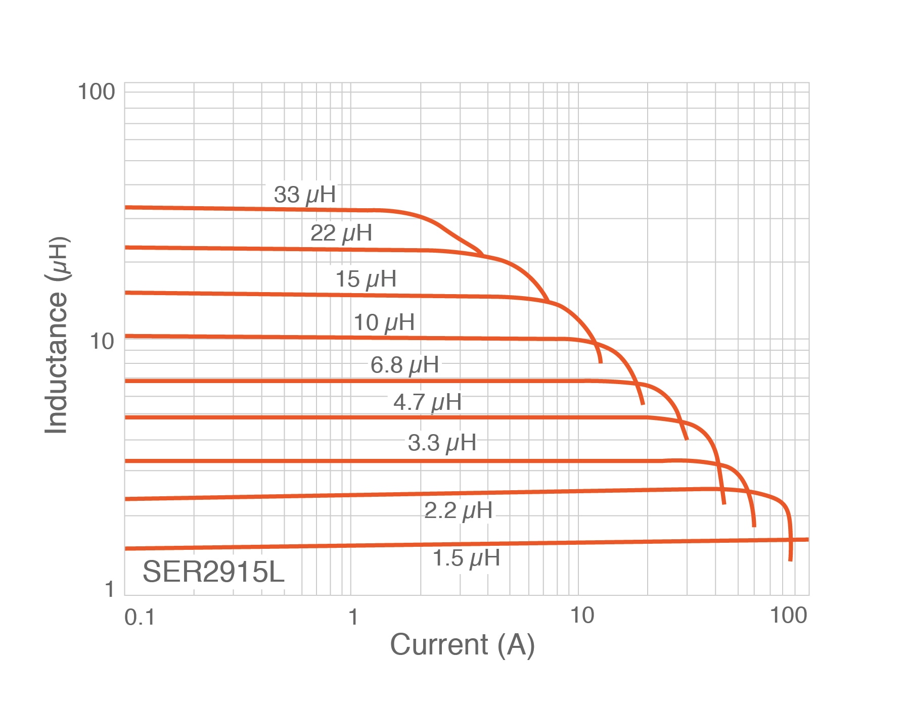
Figure 3: Inductance versus current
Image Source: http://www.coilcraft.com/pdfs/ser2900.pdf
The IRMS rating is related to how much current the inductor can handle without excessive heating. IRMS is related to the copper losses, typically how much temperature rise the conductive current losses cause.
Current ratings make assumptions about ambient temperature. Generally an inductor is only specified to run at full current at room temperature. Current ratings are derated at higher temperatures. Datasheets have derating curves (see figure 4) that show how much current an inductor should be allowed to conduct at given ambient temperatures.
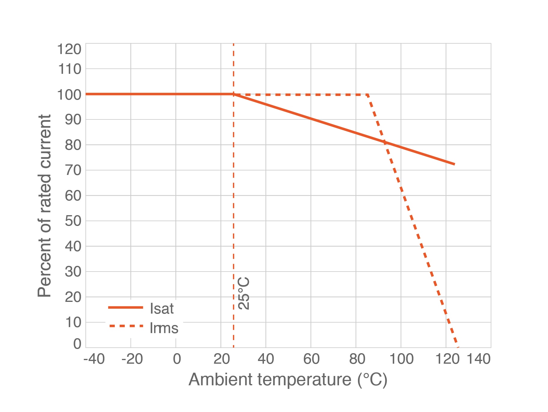
Figure 4: Current versus temperature derating
Image Source: http://www.coilcraft.com/pdfs/ser2900.pdf
Some datasheets have inductance versus frequency graphs. Inductance drops with current; this is related to core saturation. Inductance is flat over a region, then will increase. Be sure that the inductance is what you think it will be in the frequency regime where your circuit will operate.

Figure 5: Inductance versus frequency derating
Image Source: http://www.coilcraft.com/pdfs/ser2900.pdf
Winding up
Inductors are not quite as simple as our professors led us to believe. Inductors have multiple loss mechanisms, and are frequency- and current-dependent. If we take these non-ideal behaviors into consideration, then the rules we learned in college are close enough to being true to be useful and we can use them in our designs. To find the right inductor for your next project, browse DigiKey’s vast selection of inductors here: https://www.digikey.com/en/products/category/inductors-coils-chokes/4
Have questions or comments? Continue the conversation on TechForum, DigiKey's online community and technical resource.

