How Do Inverters Work?
2022-04-28 | By Dandeniyage Dasith Rajev De Silva
To explain the mechanism of an inverter, I think it's pertinent to talk about the purpose of an inverter. To do that, we need to understand the difference between AC and DC power supplies.
When science teachers explain the basic idea of electricity in high school, they typically refer to direct current (DC). DC is similar to a group of ants carrying bits of energy in the same way they carry leaves around. Imagine these ants connected in a closed loop collecting leaves from a plant and delivering them to their home. This models a DC circuit with the plant serving as the battery – supplying leaves/energy – and their home acting like the lamp or the load on the circuit – which uses up the leaves/energy. The ant and leaf analogy works sufficiently to explain simple circuits, like flashlights powered by batteries. However, when we bring in the idea of powering more complex circuits, like the ones employed in household appliances, this analogy breaks down.
This is because the main supply that powers these appliances is based on alternating current or AC. In this case, current switches direction between 50 and 60 times each second. Visually, this is what that looks like:
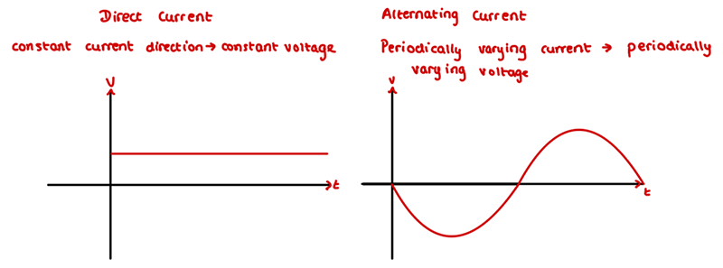
The ant analogy breaks down here: if they keep changing direction forward and backward, how would they ever deliver the leaves to their home, or in the case of an actual circuit, how do they supply power to the load? This means another analogy is required. To this end, I present a chainsaw versus a hand saw. If we imagine DC as a chainsaw where the sharp blades travel in just one direction providing energy/cutting the material and then return to their original starting point before doing this again in a closed loop, then we can analogize AC as a hand saw, where the sharp blades move forward and backward, providing energy/cutting the material in both directions, but each blade doesn’t actually travel very much. Their net displacement is actually zero.
Now we are almost ready to start talking about inverters. But before that, I think it's fair to explain why an inverter is actually needed, as I think this would provide a good segue into its inner workings – and I like good segues - so bear with me. In essence, an inverter is used to convert DC to AC. A very common use of inverters is in photovoltaic arrays since the output of these generators is DC, while all major appliances use AC power. A much more complicated use of inverters is in the speed/torque controllers in AC motors.
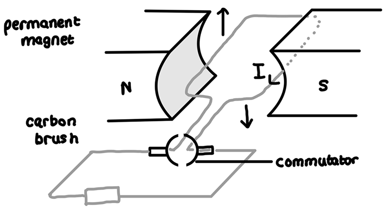
Conventionally, in a motor like this one, when current is passed through the wire as per Fleming’s right-hand rule, a force is applied to the wire causing it to turn in one direction – say clockwise. However, when it reaches the top of a revolution, the force is pointing straight upwards which means it won’t continue turning. As such we need the force to be facing down now. This is achieved by flipping the direction of the current. In a conventional DC brushed motor, this is achieved using what’s known as a split ring commutator. The only reason I remember that is because it was the coolest thing I knew how to say in high school other than Beyblade. A split ring commutator is essentially a physical switch that flips the current direction. Now, this is where our inverter comes in. An inverter’s job is to replicate this switch but with no real moving parts.
How Does an Inverter Work
For explanatory purposes, let's use a very simple circuit with a DC power supply trying to run an AC load (a lamp or a motor). This would be impossible since an AC load will not work with a DC supply. So to convert DC to AC in this example, we use 4 switches.
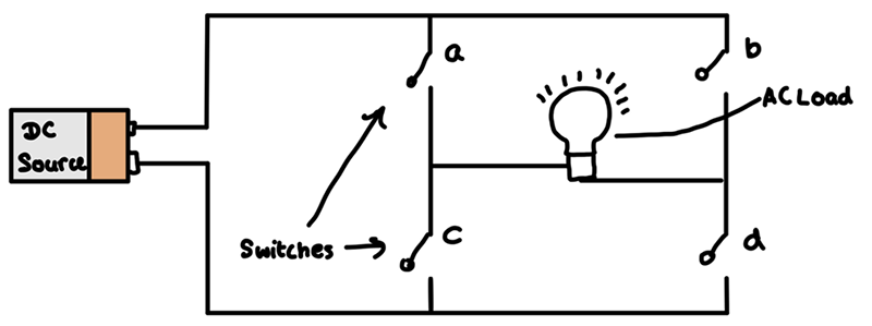
They are paired together so switches b and c open together when a and d close. As such, when switches b and c open and switches a and d are closed, this would cause current to flow through the left side of the load. Similarly, when switches a and d are open and b and c are closed, the current will only flow on the right hand of the load.
As such, though the source is DC, the load will experience an AC supply of power.
The above example is a very simple inverter, one much too simple for commercial use for 2 reasons: switching speed and the lack of a sine wave output.
Fixing Switching speed
For almost all commercial appliances, an AC supply of 50 to 60 Hz is required, and it is impossible to expect humans to be able to click all those switches at that speed. We use electronics components like diodes, IGBTs, and MOSFETs to achieve this insane switching speed.
Fixing the lack of a sine wave output:
The output of this inverter would not be a sine wave, but would rather be a square wave due to the sudden switching. This is not desirable as it can cause damage to electrical components and, as such, these sharp signals need to be shaped into a smoother sine wave. The technology used to achieve this is called Pulse Width Modulation.
Pulse Width Modulation (PWM)
SEGUE ALERT:
The output of these inverters is digital, meaning it has exactly two positions, on or off. Therefore, a square wave results from its use. Most electrical components use analog signals, meaning they can be on, off, or any value in between. So sending a digital signal to an analog device will prevent the device from behaving as intended and sometimes can have undesired effects on electronics.
SEGUE OVER:
PWM is a technology used to mimic the output of an analog modulating signal using a digital signal. In essence, PWM is able to imitate an analog output by outputting pulses of regulated voltage.
A PWM-controlled analog device will experience the average of the input pulses. This theory can be used to keep the average voltage constant – DC, or changing/varying over time – AC. How is this done? By varying the duty cycle and frequency of the input waveform. When the input signal is high, this is referred to as on-time and conversely referred to as off-time when it's low. The duty cycle percentage is an indication of what percentage of the period of the wave the signal is on. For example, if a signal is on for half a period and off for the other half, it has a duty cycle of 50% - pretty neat.
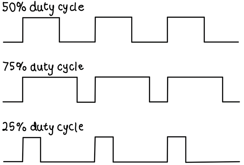
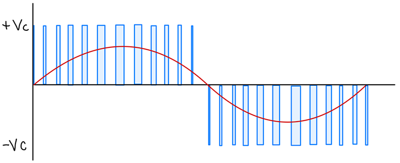
By varying the duty cycle of the input waveform, the output can be modulated to look like a sine wave.

In this case, the red line is the wave that the analog device experiences and is the average of the blue pulses at any given time. This idea of “instantaneous average” is a nod to the idea that dynamic change is occurring. One of two things can be done in this case to change the signal the analog device sees, increasing the duty cycle, and increasing the frequency serve to do the same thing in increasing the average voltage seen by the analog device. The parameter that isn’t changing is the max voltage of the input.
So how does this link to inverters? Well, since an inverter outputs a square wave, we can change its frequency and duty cycle to mimic any analog signal we want.
Types of Inverters
As usual in the real world, striving to match the ideal model of a device gets expensive and has led to two types of inverters. The first is True or Pure Sine Wave Inverters (PSW), and the second is Modified/Quasi Sine Wave Inverters (MSW). The first type is the closest we have to a perfect inverter, and they use toroidal (donut-looking) transformers to convert a DC signal into a very smooth alternating current. An MSW costs less to produce by using lower-cost components, such as thyristors and diodes to create, a “rounded off” square wave. These types of inverters can sometimes be safely used in large electronics but can very easily damage or even destroy delicate electronics – especially those with microcontrollers like laptops and smartphones.

What does an inverter look like?
Inverters are often quite large, especially if they have built-in battery packs to allow them to work without reliance on the grid. Furthermore, they produce a lot of heat and have massive passive heat dissipation components like heatsinks and sometimes even have to employ active cooling methods like cooling fans.
Just like all components, inverters can be bought to fulfill different power requirements, and this will change their size and overall footprint. But to be safe, inverters are usually bought to have a rated power of about 25% higher than the maximum power the load is expected to need. This is due to the fact that some appliances have very large turn-on powers for a short period of time. But very few of these commercial inverters are designed to work at peak power continuously.
This is by no means a comprehensive explanation of inverters and PWM, but I hope it serves as a high-level introduction to what inverters are and the underlying theories that allow them to work in the real world.

Have questions or comments? Continue the conversation on TechForum, DigiKey's online community and technical resource.
Visit TechForum


 中国
中国