Adding Short Circuit Protection to a Step-Up Converter
2016-02-23 | By Maker.io Staff
Boost converters are used widely in battery-powered electronics, but suffer from an inherent susceptibility to short circuit on the load caused by a conductive path through the output diode. This paper describes methods of adding short circuit protection including using external MOSFETs and load switches to disconnect the boost during a short circuit condition. This paper also gives two examples of boost converter ICs with built-in short circuit protection, and discusses the SEPIC and buck-boost converter as alternative topologies to the boost converter.
The boost converter
The boost converter is a step-up converter, meaning that it produces a higher voltage on its output than on its input. The boost converter suffers from vulnerability to short circuits. If VOUT is grounded, VIN is shorted to GND through the output diode D. This converter contains no means of stopping the short without adding external components. Figure 1 is a simplified schematic of the boost converter.

Figure 1: Simplified schematic of a boost converter
Protection with external MOSFET
Short circuits can be disconnected by using an external MOSFET, as shown in figure 2. In this case, an N-channel MOSFET is used as a switch to allow power to the boost converter. An external positive bias and control circuitry are required to turn the MOSFET on and off. A P-channel MOSFET can also be used. In this case, the gate can be grounded if VIN is high enough to allow sufficient voltage between the gate and source to turn the MOSFET fully off, or driven negative. In either case, the designer should take care to ensure that the MOSFET body diode opposes current flow from VIN to VOUT, or else the MOSFET does nothing to protect against short circuits on the output.

Figure 2: Simplified schematic of a boost converter with external MOSFET for short circuit protection
Protection with external load switch
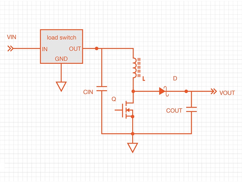
Using a load switch with integrated control circuitry simplifies the design by integrating bias and control circuitry. Some load switches include programmable current limits that trigger the load switch to turn off, disconnecting VIN from the boost converter. Some include open-drain fault pins to indicate that an overload/short circuit event has occurred. See figure 3 for a simplified example of using a load switch for short circuit protection.

Figure 3: Simplified schematic of a boost converter with external load switch for short circuit protection
Boost converter ICs with built-in protection
There are a few boost converter ICs that include integrated short circuit protection. Examples include Texas Instruments’ LM4510 and TPS61080. See the datasheets for more information.
SEPIC converter as an alternative to the boost converter
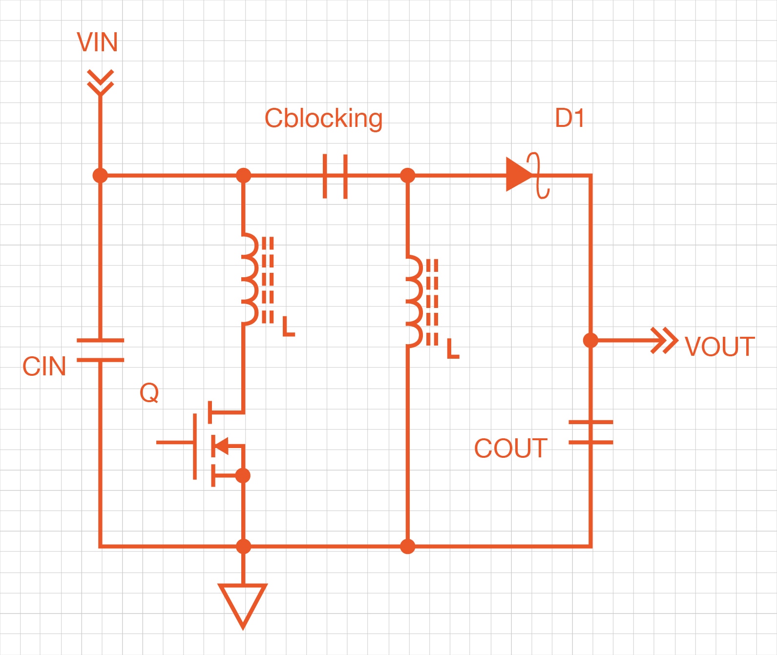
The SEPIC is a step-up/step-down DC-DC converter. This level of flexibility isn’t really needed in a purely step-up application, but the SEPIC has built-in short circuit protection. See figure 4, a simplified schematic of a SEPIC converter. If VOUT is grounded, the blocking capacitor allows only AC current to be conducted to the output. The circuit can be entirely disabled by turning of MOSFET Q. A boost converter can be modified to be a SEPIC converter by adding a capacitor between the VIN and the output diode’s anode, and by adding an inductor between ground and the diode’s anode. PCB space and cost can be reduced by using a coupled inductor, which is two windings on one magnetic core. Careful care should be given to the selection of the blocking capacitor with a high ripple current rating, as all the power flows from the input to the output through this capacitor.

Figure 4: The blocking capacitor provides inherent short circuit protection for the SEPIC converter
Buck-boost converter as an alternative to the boost converter
A buck-boost can be used. As seen in the simplified buck-boost circuit in figure 5, Q1 and Q2 are driven at the same time; D1 and D2 provide a current path. This circuit will produce a voltage higher or lower than the input. The circuit can be turned off completely by stopping switching action, which provides short circuit protection. However, this circuit uses four switches instead of two, and tends to be less efficient than a boost, take up more room, and cost more.

Figure 5: Simplified buck-boost circuit
Conclusion
The boost converter is susceptible to shorts on the output. There are many ways to produce a step-up converter with short circuit protection. A blocking MOSFET or load switch can be used to disconnect the boost converter from a short circuit. There are also commercially available ICs with built-in short circuit protection. Alternative topologies such as the SEPIC and buck-boost converters provide short circuit protection.
Have questions or comments? Continue the conversation on TechForum, DigiKey's online community and technical resource.


