Design and Build a Simple Analog LED Flasher Circuit
2022-07-13 | By Maker.io Staff
This article introduces you to a simple analog blink circuit that is a true classic for those learning about electronics. Many engineering students build this circuit as their first project, as it only comprises a handful of commonly available and inexpensive components, and the effects of swapping out parts are immediate. This simple circuit can teach you a lot about transistors, capacitors, LEDs, and resistors and how these components operate.
A Real-World Example of the Simple Flash Circuit
The astable multivibrator circuit is an incredibly versatile and simple tool in every electrical engineer's toolbox. It can be employed in a wide array of situations whenever you want to alternate between two components where only one of them is active at a time. This article uses the astable multivibrator to flash two LEDs. As mentioned, this simple blink circuit only requires a few components:
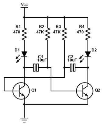 This image shows the schematic diagram of the astable multivibrator blink circuit.
You can think of a real-world example use case for this circuit when looking at one of the many railroad crossings with two alternating flashing lights that alert drivers and pedestrians of an approaching train.
Understanding the Astable Multivibrator Circuit
The schematic diagram above contains two LEDs, two NPN transistors, two non-polarized capacitors, and four resistors. The two 47k resistors and the capacitance of C1 and C2 determine the charging time of the two capacitors, while the two 470 Ohm resistors are there to limit the current flowing through each LED. The circuit is called an astable multivibrator because it doesn’t remain in one of its two well-defined states. Instead, it oscillates between one of two states where the left LED only lights up when the left transistor is active. Similarly, the right LED turns on whenever the right-hand side transistor is active. The circuit switches between these two states indefinitely as long as it’s powered.
As a side note, unfortunately, it is practically impossible to tell how exactly the circuit will behave when you first plug it in. You can precisely control all values and the startup state in a simulator. However, in reality, slight differences in the component values, temperature differences, and manufacturing inaccuracies determine how the circuit starts up. Regardless, eventually, the circuit reaches one of the two well-defined states from where it oscillates between the two possible states indefinitely. For now, assume that the circuit is in the stable state in which the right LED is on, the left LED is off, and that you can measure the following voltages:
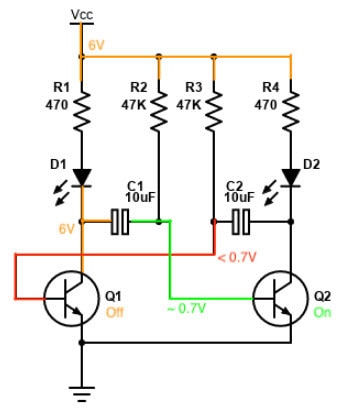 This figure illustrates the first stable state of the circuit. Assume that the circuit starts in this state when it’s first powered on.
Q1 is switched off in this state, and thus D1 is off too. With the left side of C1, Q1’s collector voltage rises towards VCC through R1. However, there’s no current flowing through R1 or D1 because Q1 is cut off. The other side of C1 sits at a potential of around 0.7V, which is enough to make Q2 reach its saturation mode and turn on D2. C1 has a voltage difference of +5.3V across its two plates in this state.
Meanwhile, C2 starts charging up through R3 exponentially, which means that the capacitor quickly reaches a voltage close to VCC. Still, it takes a capacitor significantly longer to charge up beyond that point until it almost reaches a potential of +6V. However, eventually, the left plate of C2 will reach the saturation voltage of 0.7V and turn Q1 on. As soon as that happens, the voltage on C1’s right plate (which connects to the base of transistor Q2) gets pulled down to a negative voltage. When this reverse charge is applied to Q2, it causes the transistor Q2 to turn off immediately. Note that you have to ensure that your transistors can handle the negative voltage fine to prevent the parts from getting damaged. The same applies to capacitors, especially when you’re using electrolytic capacitors.
As soon as this switch happens, D2 turns off, and D1 lights up instead. At this point, Q2 is off, and C1 begins charging in the opposite direction through R2. Here, the circuit has reached its second well-defined state. Once the base of Q2 reaches its saturation voltage of around 0.7V, the whole process repeats in reverse — as soon as Q2 switches on, C1 is suddenly discharged, which pulls Q1’s base to -5.3V and shuts off D1 and turns D2 back on again. The circuit repeats these steps as long as it’s powered on.
How Different Component Values Affect the Circuit
Use the same values for C1 and C2 and R2 and R3 to get symmetric on and off times for both LEDs. You can change the component values on one side to make the LED on that side of the circuit turn on for shorter or longer periods. In general, increasing the values of R2 and R3 causes the capacitors C1 and C2 to charge more slowly, which causes each LED to stay lit for more time while the other one stays off. You can achieve the same effect by increasing the capacitance. In general, you can work out the on/off times of the LEDs by using the following formula:
 Use this formula to calculate the on/off times of the LEDs in the blinking circuit.
So, in the circuit diagram above, each LED will stay on and off for approximately half a second.
Summary
This simple astable multivibrator blink circuit is a fantastic project for getting started with electrical engineering. Firstly, the effects of swapping out components can immediately be seen without using any measuring equipment. Secondly, the circuit might seem uncomplicated and trivial at first, but upon closer inspection, it presents a fantastic playground for figuring out and practicing calculations in real-world electronic circuits.
In simple terms, the two transistors in the circuit each control one LED. While one capacitor is charging up, the transistor on the other side of the circuit is off, and thus, the LED connected to that capacitor is also off. When the charging capacitor reaches the transistor’s saturation voltage, the transistor turns on the LED, which causes the second capacitor to draw the other transistor’s base to a negative potential, which immediately turns off the LED that was previously on. Therefore, the two LEDs blink in an alternating pattern as long as the circuit is powered on.


