Intro to FreeCAD Part 2: Sketches, Constraints, and Part Design
2024-12-19 | By ShawnHymel
In the first part of this series, we explored the history of FreeCAD and why it might be the ideal CAD software for your projects. Now, it's time to roll up our sleeves and create our first design. In this tutorial, we'll guide you through using the Part Design Workbench to create a simple SD card holder. By the end, you'll not only have a practical item but also the foundational skills to tackle your own projects, such as designing a pen cup to organize your desk.
Note that this series was made with FreeCAD v0.22 (or v1.0RC1). We recommend using that version or later, as it fixes the topological naming problem. If you use a later version, note that some of the tools and icons might be different.
Getting Started with FreeCAD
Launch FreeCAD and Set Up Your Workspace
- Ensure you're using the latest version (preferably version 0.22 or 1.0).
- You'll see a welcome screen; for now, you can ignore the extra options and focus on the default settings.
1. Open FreeCAD:
- Go to File > New or click the New Document icon.
- This document acts as your project file, containing all your designs and parts.
2. Create a New Document:
- Use the workbench selector at the top to choose Part Design.
- Notice how the toolbar and menu options change to reflect tools specific to part design.
3. Select the Part Design Workbench:
Understanding Bodies and Sketches
- Body: Represents a single contiguous shape defined by features and sketches. You can have multiple bodies within a document.
- Sketch: A 2D drawing that serves as the foundation for 3D features.
Designing the SD Card Holder
Step 1: Create a New Body
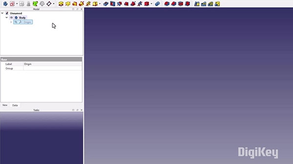
- Click the Create Body icon in the toolbar.
- A new body appears in the Model Tree on the left.
1. Create Body:
- If you have multiple bodies, right-click on the one you want to work with and select Set Active Body.
- The active body is highlighted, indicating it's ready for new features.
2. Activate the Body:
Step 2: Start a New Sketch
- Click the Create Sketch icon.
- A dialog prompts you to select a plane. Choose the XY plane.
- Click OK to enter the Sketcher workbench.
- The X-axis is red, and the Y-axis is green.
- The origin is marked by a blue dot.
1. Create Sketch:
2. Understanding the Sketcher Interface:
Step 3: Draw the Base Rectangle
- Click the Rectangle icon in the toolbar.
- Click to set the first corner near the origin.
- Click to set the opposite corner.
- Press Esc or right-click to exit the rectangle tool.
1. Select the Rectangle Tool:
2. Draw the Rectangle:
Step 4: Apply Constraints to the Sketch
Constraints define the dimensions and relationships of your sketch elements, ensuring precision.
- Select the Symmetric Constraint icon.
- Click on the two diagonal corner points of the rectangle.
- Then click on the origin point.
- This centers the rectangle around the origin.
- Horizontal Distance:
- Click the Horizontal Distance icon.
- Select the top or bottom edge of the rectangle.
- Enter 29 mm and click OK.
- Vertical Distance:
- Click the Vertical Distance icon.
- Select one of the side edges.
- Enter 42.8 mm and click OK.
- Ensure the sketch status shows Fully Constrained (no degrees of freedom left).
- This means all elements are precisely defined.
1. Symmetric Constraint:
2. Dimension Constraints:
3. Fully Constrained Sketch:

Step 5: Pad (Extrude) the Sketch
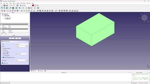
- Click Close in the tasks pane to return to the Part Design workbench.
- With the sketch selected, click the Pad icon.
- In the dialog:
- Set Length to 18 mm (height of the holder).
- Click OK.
- The 2D sketch is now a 3D solid.
1. Exit the Sketcher:
2. Pad the Sketch:
Step 6: Create the SD Card Slots
a. Start a New Sketch on the Top Face
- Click on the top surface of the padded solid in the 3D view.
- Click the Create Sketch icon.
- The new sketch is attached to the selected face.
1. Select the Top Face:
2. Create Sketch:
b. Bring in External Geometry
- Click the External Geometry icon (looks like a pink line with an edge).
- Click on the top horizontal edge and the left vertical edge of the base.
- These edges appear as pink dashed lines in your sketch.
1. External Geometry Tool:
2. Select Reference Edges:
c. Draw the Slot Rectangles
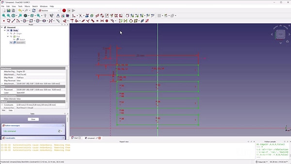
- Use the Rectangle tool to draw four rectangles above the X-axis.
- They don't need precise positions yet.
1. Draw Four Rectangles:
d. Apply Constraints to the Slots
- Use the Equal Length constraint to make all rectangles the same size.
- Select corresponding sides (e.g., all top edges) and apply the constraint.
- Use the Vertical Constraint to align the left sides of the rectangles.
- Toggle Construction Mode by clicking the Toggle Construction Geometry icon.
- Draw vertical lines between the bottom corners of the slots to define equal gaps.
- Slot Width:
- Set the width (horizontal distance) of a slot to 3.1 mm (SD card thickness plus tolerance).
- Slot Length:
- Set the length (vertical distance) to 25 mm (SD card width plus tolerance).
- Gap Between Slots:
- Set the vertical distances between slots to 2 mm.
1. Equal Constraints:
2. Vertical Alignment:
3. Construction Geometry:
4. Dimension Constraints:
e. Mirror the Slots
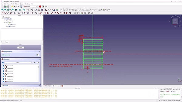
- Drag a selection box around the four rectangles.
- Click the Symmetry icon.
- Select the X-axis as the mirror line.
- Four additional slots appear below the X-axis.
- Ensure the mirrored slots are fully constrained.
- Use Equal and Vertical constraints as needed.
1. Select All Slot Elements:
2. Symmetry Tool:
3. Apply Necessary Constraints:
f. Finalize the Sketch
- Check that the sketch is fully constrained.
- Click Close to exit the Sketcher.
Step 7: Create Pockets for the Slots
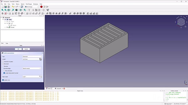
- With the slot sketch selected, click the Pocket icon.
- Type: Select Dimension.
- Length: Enter 16 mm (desired depth of the slots).
- Click OK.
- Rotate the 3D view to inspect the slots.
- The slots should be cut into the base to the specified depth.
1. Pocket Tool
2. Set Pocket Parameters:
3. Review the Model:
Saving and Exporting Your Design
Step 1: Save Your Project
- Go to File > Save As.
- Name your project (e.g., SD_Card_Holder.FCStd).
- Click Save.
Step 2: Export for 3D Printing
- Click on the Body in the Model Tree.
- Go to File > Export.
- Choose STL Mesh from the file type dropdown.
- Name the file and click Save.
1. Select the Body:
2. Export as STL:
Preparing for 3D Printing
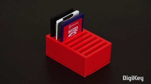
Optionally, you can 3D print your design to get a usable SD card holder. Feel free to check out our Introduction to 3D Printing series to learn more!
Step 1: Load the STL into a Slicer
- Open your preferred slicing software (e.g., Cura, PrusaSlicer).
- Import the STL file.
Step 2: Adjust Print Settings
- Orientation:
- Ensure the model is oriented with the slots facing upward.
- Supports:
- Supports are generally not needed for this design.
- Infill and Layer Height:
- Adjust according to your preferences and printer capabilities.
Step 3: Slice and Export G-Code
- Slice the model to generate the G-Code.
- Review the estimated print time and material usage.
- Save the G-Code file.

Step 4: Start Printing
- Transfer the G-Code to your 3D printer.
- Begin the print.
- Monitor the print to ensure the first layers adhere properly.
- Admire your work!
Challenge: Design Your Own Organizer
Now that you've mastered the basics, it's time to apply your skills to a new project.
Project Idea: Pen Cup
- Experiment with the Circle and Arc tools in the Sketcher.
- Think about the dimensions needed to hold pens and pencils.
- Consider adding compartments or decorative elements.
- Fully constrain your sketches to ensure precision.
- Use Pad, Pocket, and other tools to shape your design.
1. Create a New Document in FreeCAD.
2. Use Circles and Arcs:
3. Design Considerations:
4. Apply Constraints:
5. Create 3D Features:
Share Your Creation
- Take a Screenshot or Photo of your model or printed object.
- Share on Social Media (X, Instagram, LinkedIn):
- Use the hashtag #DKFreeCAD and tag @DigiKey
- Tag relevant accounts to showcase your work.
Conclusion
Congratulations! You've successfully designed and (potentially) printed an SD card holder using FreeCAD. You've learned how to:
- Navigate the Part Design Workbench.
- Create and constrain sketches.
- Use features like Pad and Pocket to turn sketches into 3D models.
- Apply symmetry and construction geometry to simplify complex designs.
These foundational skills are crucial for any CAD project. As you continue to explore FreeCAD, you'll discover more advanced features and techniques.
What's Next?
In the next tutorial, we'll delve into using Shape Binders and working with multiple bodies. This will enable you to create more complex assemblies, such as enclosures with lids.


 中国
中国