Designing for 3D Printing: Tips and Tricks
2021-08-11 | By Maker.io Staff
The selection of the correct filament type and the preparation of the 3D printer are only the first steps to achieve perfect results with 3D printing every time. Designing the parts with 3D printing as the manufacturing method in mind is equally important for good results. A design that is not optimized can make it very difficult, if not impossible, to manufacture a part using a 3D printer. This article summarizes a few tips and tricks that will allow you to design components that are easy to print in no time!
Physical Limitations of the Manufacturing Process
As with every other manufacturing process, 3D printing is well-suited for realizing specific designs. Even though 3D printing is generally more flexible than many other manufacturing processes (such as using a lathe), there are still a few physical limitations to keep in mind. The most obvious one is the size of the printer’s build area. The printer can’t manufacture parts that protrude over the boundaries of its build area.
A little less obvious limitation of FDM 3D printers comes from the fact that they build each part one layer at a time. The layer size influences the accuracy of the printed components and tolerances. Therefore, try to design with the intended layer height in mind. If you plan to use a layer height of 0.3mm, for example, then you should use multiples of that layer height in your design if possible. Doing so will make it easier for the slicing software to cut your part into individual layers, and the 3D printer will produce more accurate results.
Unfortunately, it’s not always possible to design components using the intended layer height, for example, when you’re trying to create a replacement part that precisely needs to fit into an existing system. When this is the case, try to design with tolerances in mind. The tolerances can vary dramatically depending on your 3D printer and the material of choice. Some printers are more accurate than others, and some materials, such as ABS, are more prone to shrinking than PLA, for example.
Part Design Considerations
Whenever possible, try to include a flat edge in your design. Then, in the slicing software, lay the part so that the flat edge sits on the printer’s manufacturing area. Using a flat edge makes it easier for the printer to put down the first few layers, which are crucial for successful prints. Note that this trick is not suitable for some applications, such as manufacturing replacement parts. Then, I recommend thinking about custom support structures.
If your 3D printer has a dual-extruder print head, you can try using soluble support materials that work well with your printer and part. However, it's also possible to use the same material to print the component and its support structure. Keep in mind that this solution sometimes doesn't work as intended, as the support material tends to be too difficult to remove after the print. You can also manually design support structures in your 3D modeling or CAD program:
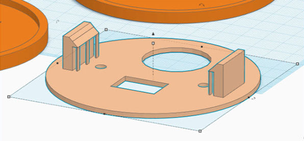 Custom supports on a simple 3D design created with Autodesk Tinkercad.
Chamfers and Fillets
I recommend adding chamfers or fillets to models that you want to 3D print. Most 3D modeling and CAD software support chamfers and fillets, and they have a few positive effects. Instead of creating 90° edges on a model, a chamfer creates a 45° angle along one or more edges of a part. The fillet tool works similarly. It, however, produces a curve rather than a 45° angle, which leads to rounded edges:
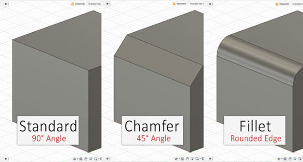
These rounded edges and chamfers on the outside edges of a model not only look more natural and visually pleasing, but they also have the positive side-effect of leading to 3D printed parts that waste less material, typically without sacrificing any strength.
Using fillets and chamfers is especially important when your model has overhangs. These techniques reduce the amount of material suspended in the air during a print, which leads to an increase in print quality. It's less difficult to print a model with 45-degree angles or rounded edges compared to one with 90° overhangs:
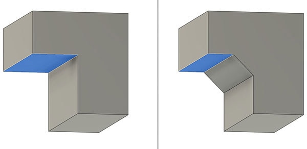 The example on the left contains a single large 90° overhang. Most 3D printers will have problems printing this part in that orientation. On the right, I added a chamfer and reduced the size of the overhang. This part will be easier to print. Note that the optimal solution would be to orient the component differently so that there's no overhang when printing. This example serves as a demonstration.
Besides these benefits, chamfers and fillets allow snap-in parts to fit together more easily, thus reducing the mechanical stress on the snap-fit connections during the assembly process.
Additional Tips and Tricks
For particularly complicated pieces, such as exact replacements for intricate components, I like to determine the measurements of the replacement part first. Then, I use CAD software to build a rough model with the exact measurements that I took earlier. I then create a small test piece for 3D printing that helps me verify that my measurements and the tolerances are correct and that the material and 3D printer behave as expected.
 The white 3D printed test piece perfectly fits around the crevices of the beige gearbox. The smaller test piece allows me to see potential problems I wouldn't be able to observe in the full motor housing.
Once I know that the test piece fits, I can then design the finished replacement component. This procedure helps me reduce the time needed to model the part, as I can be sure that the measurements are correct and that I don’t need to mess with them anymore. This strategy also helps cut down the number of prints before ending up with a part that fits.
Summary
As with every other manufacturing process, 3D printing is subject to certain limitations. The most obvious one is the size of the build plate. Another one is the accuracy of prints. Design 3D printed parts with your layer height, tolerances, and material shrinking in mind. When designing components for 3D printing, try to include at least one flat surface that will lay flat on the print bed. Doing so ensures that the printer can start the manufacturing process with a solid base that properly adheres to the print bed.
You can try using custom-made or automatically generated supports if it’s impossible to incorporate a flat surface into the design. Certain 3D printer filaments were specifically designed to be used for printing support structures that are easily detachable from the main part. Last, try to use the chamfer and fillet tools of CAD programs to create better-looking edges on 3D models. Rounded off edges and 45° angles are typically easier to print than 90° overhangs. Furthermore, rounded edges also reduce the stress on snap-fit parts when assembling them.


