Intro to FreeCAD Part 4: How to Use Heat Set Inserts
2025-01-16 | By ShawnHymel
3D Printing 3D Print Accessories 3D Printer
Heat set inserts are an excellent solution for securely connecting 3D-printed parts using screws. They provide a robust method for assembling components, particularly when you need a connection that can be disassembled and reassembled multiple times. In this tutorial, we'll explore how to design the correct-sized holes for heat-set inserts in FreeCAD using the Hole tool, and we'll guide you through the process of installing them into your 3D-printed parts.
1. Understanding Heat Set Inserts
Heat set inserts are typically made of brass and feature a knurled outer surface with internal threading. They are designed to be heated and pressed into plastic, melting the surrounding material to create a strong, embedded thread.
Advantages:
- Secure Connections: Provide strong threads within plastic parts.
- Reusable: Allow for multiple assembly and disassembly cycles.
- Professional Finish: Improve the durability and longevity of your 3D-printed assemblies.
When to Use:
- When you need a secure connection that can withstand torque.
- In assemblies that require maintenance or access.
- When threads printed directly into plastic are insufficient.
2. Designing Holes for Inserts in FreeCAD
Designing the correct hole size is crucial for effective installation and performance of heat-set inserts. CNC Kitchen has a fantastic tutorial on correctly sizing holes for heat-set inserts.
Key Considerations:
- Hole Diameter: Slightly larger than the smooth tip diameter but smaller than the knurled section.
- Hole Depth: At least 1 mm longer than the insert to accommodate melted plastic.
- Wall Thickness: Minimum of 1.6 mm around the hole for structural integrity.
Example Dimensions for an M3 Insert:
- Insert Length: 4 mm.
- Smooth Tip Outer Diameter: 3.75 mm.
- Knurled Section Outer Diameter: 4.2 mm.
- Recommended Hole Diameter: ~3.85 mm (smooth tip diameter + 0.1 mm).
- Hole Depth: 5.2 mm (insert length + 1.2 mm).
3. Creating the Base Part
We'll start by designing a base part with two posts where the inserts will be placed.
Steps:
- Open FreeCAD and Create a New Document:
- Switch to the Part Design workbench.
- Click Create New Body.
- Create a New Sketch:
- Click Create Sketch and select the XY plane.
- Draw the Base Shape:
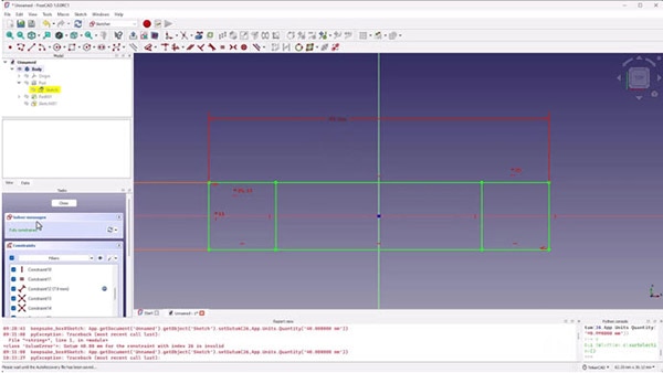
- Use the Rectangle tool to draw two rectangles representing the posts.
- Draw two horizontal lines connecting the inner points of the posts.
- Apply Constraints:
- Symmetry Constraint: Center the geometry around the origin.
- Equal Constraint: Ensure both posts are the same size.
- Dimension Constraints:
- Set the width to include the hole diameter plus wall thickness:
- Width = Hole Diameter + (2 × Wall Thickness) = 3.9 mm + (2 × 2 mm) = 7.9 mm.
- Set the length of the connecting bar (e.g., 40 mm).
- Close the Sketch.
- Pad the Base:
- Select the outer profile.
- Click Pad and set the length to 2 mm.
- Pad the Posts:
- Hide the first pad.
- Select the profiles of the posts.
- Click Pad and set the length using an expression:
- Length = Base Thickness + Post Height = 2 mm + 6 mm = 8 mm.
4. Adding Holes for Inserts
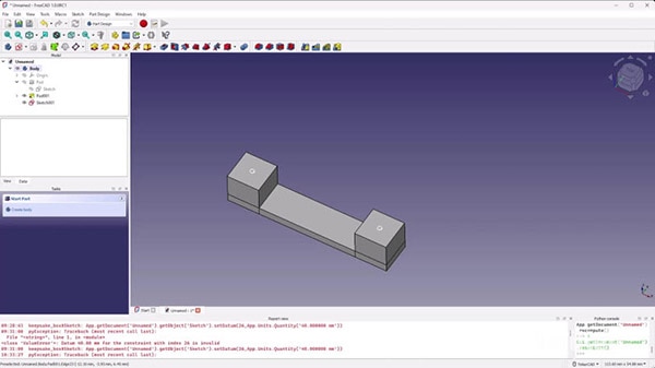
Now we'll add holes to the posts for the heat set inserts.
Steps:
- Create a New Sketch:
- Sketch on the top face of the posts.
- Use External Geometry to reference the post edges.
- Draw Circles for the Holes:
- Place circles centered on the posts.
- Set the diameter (size doesn't matter here as we'll define it in the Hole feature).
- Close the Sketch.
- Use the Hole Tool:
- Select the sketch and click the Hole tool.
- Set parameters:
- Diameter: 3.9 mm (as calculated).
- Depth: 5.2 mm.
- Drill Point: Flat (since we're 3D printing).
- Threading: None.

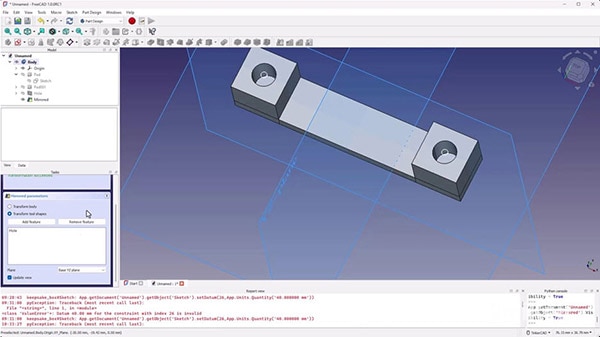
- Mirror the Hole:
- Select the hole feature.
- Click the Mirror tool.
- Choose the YZ plane to mirror the hole to the other post.
- Click OK when done.
5. Designing the Connecting Part
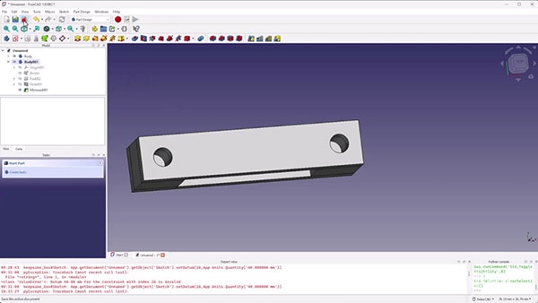
We'll create a second part that will attach to the base using screws and the inserts. You have used all of these tools before, so this should be straightforward–feel free to reference the previous section on how to make sketches, place holes, and use the mirror tool.
Steps:
- Create a New Body:
- Click Create New Body.
- Create a SubShapeBinder:
- With the new body active, select the base body.
- Click SubShapeBinder to reference the base geometry.
- Create the Top Part Sketch:
- Sketch on the top face of the SubShapeBinder.
- Use External Geometry to reference the edges of the posts.
- Draw the Top Shape:
- Draw a rectangle covering the posts.
- Close the sketch.
- Pad the Top Part:
- Pad the sketch by 2 mm.
- Add Holes for Screws:
- Create a new sketch on the bottom face of the top part.
- Use External Geometry to reference the hole centers from the base.
- Draw circles at these points.
- Use the Hole Tool for Screws:
- Select the sketch and click the Hole tool.
- Set parameters:
- Hole Type: ISO metric regular.
- Size: M3.
- Fit: Close or Standard.
- Depth: Through All.
- Mirror the Hole:
- Mirror the hole feature as before to create the second hole.
6. Preparing for 3D Printing
Steps:
- Export the Bodies:
- Select each body (base and top part).
- Go to File > Export.
- Choose STL Mesh format.
- Import into Slicer:
- Open your slicing software.
- Import both STL files.
- Arrange them appropriately on the build plate.
- Adjust Print Settings:
- Layer Height: Set according to desired quality.
- Infill: Adjust for strength.
- Supports: Generally, not needed for this design.
- Orientation: Ensure parts are oriented to minimize overhangs.
- Slice and Export G-Code:
- Slice the model.
- Save the G-code for printing.
- Print the Parts:
- Transfer the G-code to your printer.
- Begin the print and monitor for any issues.
7. Installing Heat Set Inserts
Once your parts are printed, you can install the heat set inserts.
Required Tools:
- Heat Set Inserts: Matching the holes you've designed (e.g., M3 inserts).
- Soldering Iron: With adjustable temperature and a suitable tip.
- Soldering Iron Tip: You have two options
- Special-made tip for your iron and insert. For example, this tip works with Hakko soldering stations and #4 or M3 inserts. They perfectly fit into the insert to prevent plastic from oozing into the barrel. However, you need a tip for each insert size.
- You also have the option of using a regular (flat or conical) soldering iron tip. With this setup, you have to be careful to prevent plastic from oozing inside the insert barrel.
- Screwdriver and Screws: To match the inserts.
- Pliers or Metal Tool: For handling hot inserts.
Steps:
- Prepare the Soldering Iron:
- Set the temperature to approximately 500°F (260°C).
- Use a flat or chisel tip for better heat transfer.
- (Optional) Insert a Screw into the Insert:
- Only do this if you are using a regular soldering iron tip!
- Thread a screw into the insert until it's flush with the bottom.
- This helps prevent plastic from entering the threads.
- Place the Insert:
- Position the insert (with screw) into the hole on the printed part.
- Heat the Insert:
- Press the soldering iron onto the head of the screw.
- Apply gentle pressure.
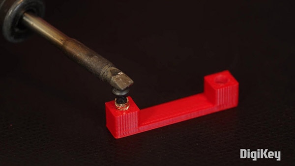
- Insert the Insert:
- As the insert heats up, it will begin to melt the surrounding plastic.
- Slowly press the insert into the hole until it's slightly below flush.
- Secure the Insert:
- Remove the soldering iron.
- Quickly use pliers or a metal tool to hold the insert in place as it cools.
- If you do have a screw in the insert, you can also use a flat, metal ruler (or spatula) to hold the insert in place, ensuring a flush fit.

- Repeat for Other Inserts.
- Remove Screws:
- Once cooled, unscrew the screws.
- Your inserts are now securely installed.
Tips:
- Safety First: Be cautious with the hot soldering iron and inserts.
- Avoid Overheating: Excessive heat can deform the part.
- Test Fit: Before final assembly, ensure screws thread smoothly.
Challenge: Enhance Your Designs
Now that you've learned how to use heat-set inserts, apply this knowledge to your previous projects.
Ideas:
- Modify the Keepsake Box:
- Add screw holes and inserts to secure the lid.
- Ensure proper alignment and fit.
- Create a Secure Enclosure for Electronics:
- Design an enclosure for a Raspberry Pi or Arduino.
- The Raspberry Pi uses M2.5 screws
- Most official Arduino boards use M3 screws
- Incorporate mounting points using heat-set inserts.
Share Your Work:
- Showcase Your Designs:
- Take screenshots or photos of your models or printed parts.
- Share on social media platforms like X, Instagram, or LinkedIn.
- Use the hashtag #DKFreeCAD and tag @DigiKey to connect with the community.
Conclusion
Congratulations! You've expanded your FreeCAD skills by learning how to design for and install heat set inserts. This technique significantly enhances the functionality and professionalism of your 3D-printed projects.
Key Takeaways:
- Heat set inserts provide strong, reusable threads in plastic parts.
- Accurate hole design is crucial for successful installation.
- FreeCAD's Hole tool simplifies the creation of holes for standard hardware.
- The Mirror feature saves time when working with symmetrical designs.
What's Next?
In the next tutorial, we'll explore using the Gear tool along with feature patterns and Boolean operations to design a custom servo motor disc. You'll learn advanced modeling techniques to create intricate and functional parts.
Have questions or comments? Continue the conversation on TechForum, DigiKey's online community and technical resource.


