制造商零件编号 A000066
ARDUINO UNO R3 ATMEGA328P BOARD
Arduino
We put a lot of effort into building our electronics projects, and a beautiful project deserves an equally beautiful enclosure. Project cases not only protect the internals from getting damaged, but they also make custom-built devices easier to handle and use in everyday life. Off-the-shelf project boxes are perfect for when you don’t have a lot of time and require a quick solution. However, nothing beats a custom-designed and manufactured enclosure to round off your DIY projects, and this article discusses how you can design beautiful cases in Fusion360.
You can have a look at this article that compares various CAD options for makers if you’re unsure whether Fusion360 is the correct tool for you. Have a look at this article if you decide to go with Tinkercad. It outlines the case design process using Tinkercad instead of Fusion360
Fusion360 is a professional-grade accurate CAD tool for designing components for various applications. Therefore, it’s crucial that you carefully plan your case design and take note of the dimensions of all parts you want to fit in the enclosure. So, before you get excited and do anything else, make sure to accurately take and note the dimensions of the parts you want to fit in the case.
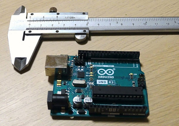 Use an accurate caliper to determine the exact dimensions of the components.
Alternatively, you can also search for a technical drawing of the components you want to mount in your custom case. You can often find detailed illustrations in the component’s datasheet or the manufacturer’s documentation. DigiKey also offers 3D EDA/CAD models for many products that you can directly import to your CAD program.
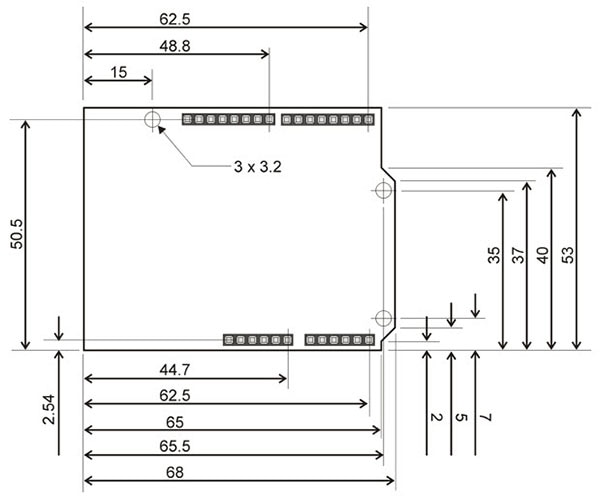 I recommend you try to find technical drawings of the components you want to use. Verify the correctness of the dimensions with your caliper. All dimensions in this image are in millimeters. Image source
Write the dimensions on a piece of paper or directly transfer them to Fusion360 as you go along.
Once you’ve determined the exact measurements of the components in your design, it’s time to create a technical drawing according to those numbers. In Fusion360, use the view cube in the top-right corner to allow the camera to go into top-down view mode. Then, click the ‘Create Sketch’ button and start a new sketch on the visible plane:
 Follow these instructions to start a new sketch. The third step tells Fusion360 that you want to use this plane for sketching. You can use different planes to create cutouts, as I’ll demonstrate later in this article.
You can see how the top toolbar changes when starting a new sketch. Use the tools in the top toolbar to create the outlines of the Arduino UNO in Fusion360. Use the measurements you obtained earlier for reference:
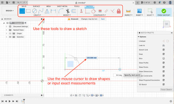 Use the sketch tools to create a technical drawing of the components in Fusion360.
You can use the line tool to recreate more complex shapes, such as the outline of the Arduino UNO. For parts with a simpler shape, such as the Arduino Nano range of single-board computers, I use the rectangle tool to draw the rough shape of the component. You can also simplify the outline of a part by using a larger box that fits around it. Either way, use the circle tool to draw mounting holes before finishing the sketch. You don’t need to include all the details found on an Arduino. You’ll only need the outline and mounting holes:
 At this point, you should have an accurate drawing of your components in Fusion360.
Now that you have finished the Arduino outline in Fusion360, start another sketch and draw a box shape around the Arduino you made earlier. The box will be the enclosure itself. Your drawings should look something like this now:
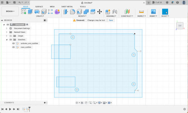 I drew a 4mm border around the Arduino. This larger box will be the enclosure.
You can now use the middle mouse button or the view-cube in the top-right corner of Fusion360 to pan the camera. Use the mouse cursor to select the outer box you just drew and then hit the "E" key on your keyboard to bring up the extrude tool:
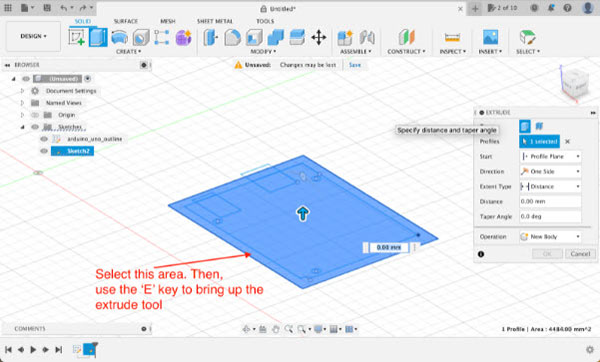 Select the outer surface and then open the extrude tool.
Use the keyboard to type in ‘20mm’, which will extrude the selected sketch by 20 millimeters along the upward-facing axis:
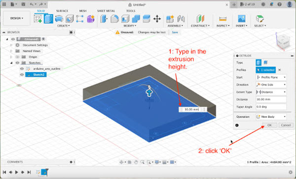 Type in 20mm to pull the selected area up and create the enclosure.
Next, select all the parts of the Arduino outline sketch you created earlier and then open the extrude tool by hitting the ‘E’ key on your keyboard. This time extrude the selected shapes by minus fifteen millimeters. Fusion automatically detects that the extruded body intersects with an existing body, and the program thus concludes that you want to create a cutout:
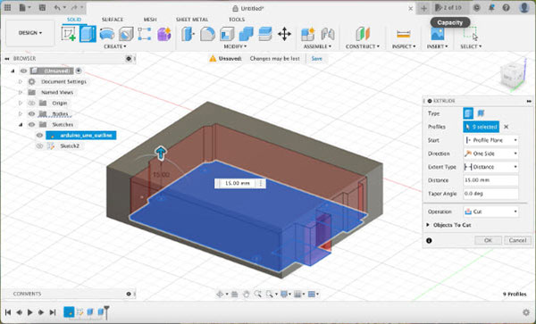 You can use the extrude tool to create cutouts and holes. Cut out the shape of the Arduino.
Once you hit enter on the keyboard, the program calculates the cutout area. Here you’ll notice that one cutout doesn’t penetrate through the shell of the enclosure. Select the inside face of that cutout and extrude it again. You can instruct Fusion360 to create a cut using a reference point in your design. Choose that option from the sidebar and click the outside wall of the enclosure to cut the hole for the power socket:
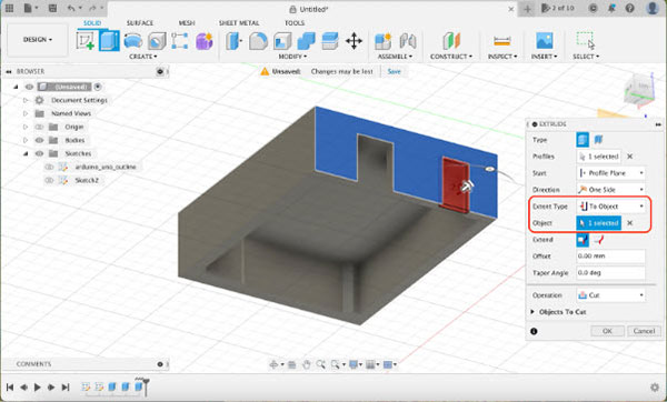 Create the missing cutout for the power connector.
Now you should have a rectangular case with a cutout that perfectly matches the size of an Arduino. The enclosure also has a cutout for the USB and power sockets on one side. I want to 3D-print this case later, so I’ll have to create some wiggle room inside the case for the Arduino. Remember that when you 3D-print an object, it typically shrinks a bit once it cools down. Therefore, I want to make the inside of the case 0.5mm larger on each side. To do that, select each of the inside walls and then open the ‘Offset Face’ tool from the top toolbar:
 Open the offset face tool to create a bit of wiggle room inside the case.
Once the tool opens, type in minus 0.5mm, and then click the ‘OK’ button:
 In the offset face tool, type in -0.5mm to account for manufacturing tolerances.
Doing so will push the inside walls 0.5 millimeters back without altering the outside dimensions of the enclosure. Next, open the mirror tool to create an identical copy of the part you just made. The result will be the bottom of the case:
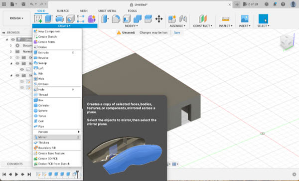 Use the top toolbar to open the mirror tool.
In the mirror tool, select all the faces of the case design. Then, select the axis you want to use to mirror the selected objects. Fusion360 displays a shadow showing you where the program will place the new body once you hit the ‘OK’ button. Make sure that the shadow appears underneath the selected objects:
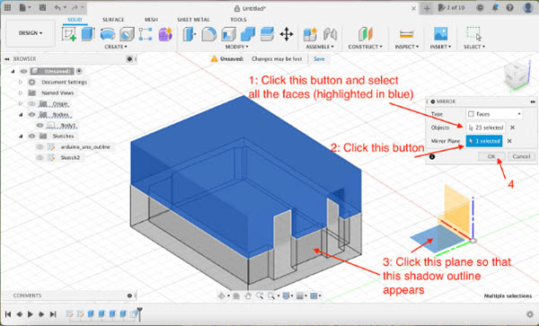 This image outlines the necessary steps to mirror parts in Fusion360.
Lastly, use the extrude tool to reduce the height of the mirrored object:
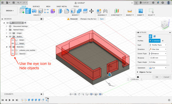 Use the extrude tool to reduce the height of the lid.
At this point, you should have two separate case pieces like this:
 You should have these two parts after using the mirror tool and the extrude tool.
As a last step, you need to create something that allows you to close the two case pieces. I incorporated a few pegs that go through the mounting holes in the Arduino. To do this, select the previously drawn circles on the Arduino outline sketch and extrude them downward until they intersect with the bottom case piece. Then, set the operation in the extrude tool window to ‘Join’ rather than ‘Cut’:
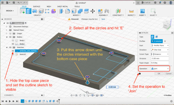 Follow these steps to create small pegs on the bottom piece of the enclosure.
 Create large pegs on the top part of the case.
Then, repeat the same steps again. However, choose the ‘Cut’ option this time when you extrude the sketch:
 Create holes in the large pegs on the top half of the enclosure.
Doing so will create a structure where the pegs on the underside of the enclosure can snap into when you close the case:
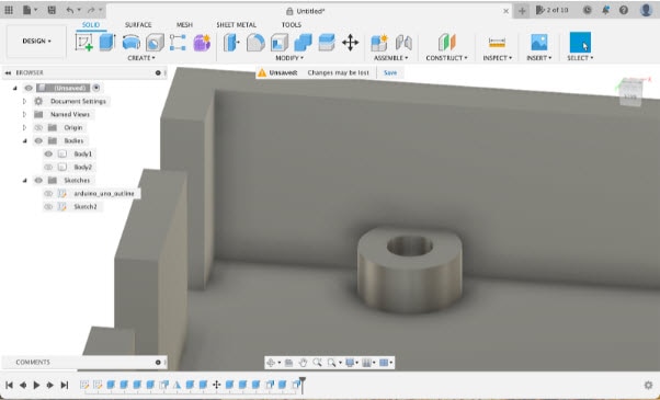 This image shows the result of the last few steps.
As the very last step, extend the pegs on the bottom half of the case so that they reach into the newly created cutouts in the top half of the enclosure:
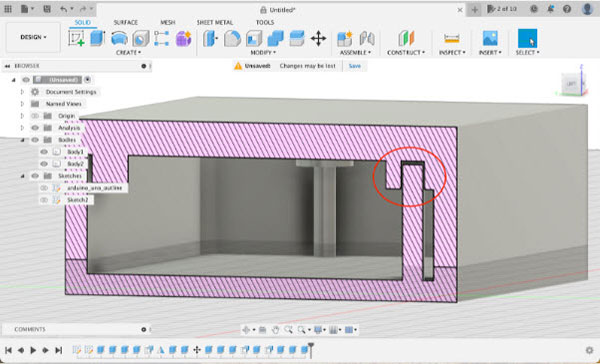 Bring up the pegs on the lower half of the case until they look like in this image. You can use the cross-section analysis tool to see inside the model.
Now that you’ve designed your first custom enclosure, it’s time to manufacture it! For most, this means 3D printing the final design. You can export each part of the design by right-clicking it in Fusion360 and then choosing the ‘Save As Mesh’ option from the menu:
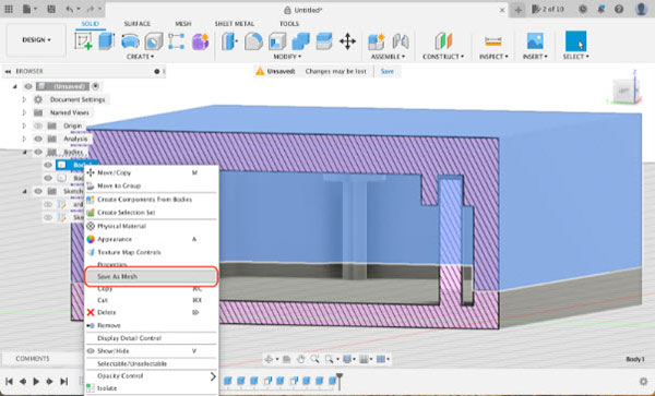 This image shows how to save a body as a mesh for 3D printing.
You can check out the following guides for some 3D printing tips and tricks that help you avoid common pitfalls when using a 3D printer:
This tutorial introduced the basic workflow of Fusion360, a professional-grade CAD program. I used a handful of the simplest tools that the program offers. Throughout this tutorial, I designed a simplistic enclosure for an Arduino UNO.
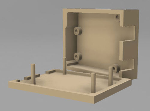 This image shows a 3D render of the finished case design.
The typical workflow in Fusion360 consists of three steps. First, you create a technical drawing of your design. Then, you use the extrude tool to create 3D bodies from your 2D sketches. Lastly, you refine the design by using various built-in tools. After completing this tutorial, you should be able to design simple enclosures for your custom projects. Note that there are usually multiple ways to accomplish a goal in Fusion360, and I opted to use the simplest ones throughout this tutorial. Feel free to experiment with the various other tools Fusion360 has to offer once you get familiar with the basics.