How To Design 3D-Printable Cases with Inkscape
2024-07-01 | By Maker.io Staff
Most professional CAD programs have a significant barrier of entry that newcomers must overcome before creating even the simplest of functional designs for their projects. While those elaborate programs are crucial for professionals and offer advanced accuracy, we usually don’t need most features to design functional parts, such as cases, for our projects. Instead, we can look into more straightforward and free software like Inkscape that offers sufficient functionality and accuracy for 3D-printed designs.
Getting Started
You should start by downloading Inkscape for your target platform and installing the program on your computer.
 Use the buttons on the Inkscape website to download the appropriate version for your operating system.
Next, find a technical drawing of the parts you want to use in your project. The drawing is necessary to ensure that the resulting sketch is accurate and that electronic components fit the designed case. Some manufacturers provide vector drawings with the technical specifications of parts. In that case, you can directly import the drawing into Inkscape and skip the next steps.
However, in most cases, you have to rely on a technical drawing provided as an image with measurements. Usually, it’s best to refer to the manufacturer’s official documentation of a part, such as the device’s datasheet.
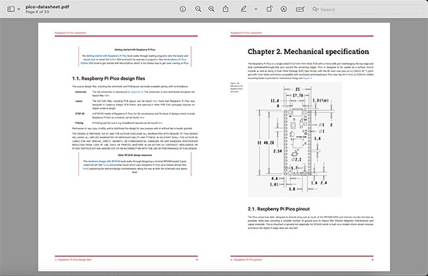 The Raspberry Pi Pico datasheet contains a detailed technical drawing describing the device’s mechanical specifications.
In the worst case, you might have to measure the parts yourself and create technical drawings from scratch.
Importing Technical Drawings to Inkscape
When first starting Inkscape, the program displays a setup assistant that lets users choose between different visual styles and icons. Once done, you can create a new document using the following assistant that’s displayed by default each time the program starts:
 Use the highlighted button to create a new vector drawing
Once the new window opens up, the previously found or created technical drawing can be imported using the program’s main menu bar and finding the import option. Before importing the file, Inkscape might ask you whether the program should adjust the scale or color space of the image. The default options work fine for this case, and the drawing should look as follows once the image gets imported:
 This image shows the imported technical drawing in Inkscape
Aligning the Drawing Size
After importing the image, you’ll need to align the drawing so that the measurements depicted in the image accurately follow the units in Inkscape. Doing so ensures that the dimensions in the drawing are true to the actual dimensions.
The easiest way is to find a set of values on the drawing with whole numbers. In this example, the board’s overall width and height work well. Start by adding a shape that matches the chosen structure, for example, a box. Create the shape by drawing it on the canvas with the mouse. Then, ensure that the shape is filled with a solid color and set the opacity to around 70% to make the shape slightly translucent. Finally, ensure that Inkscape is set to the same units as the drawing. In this case, the drawing is in millimeters.
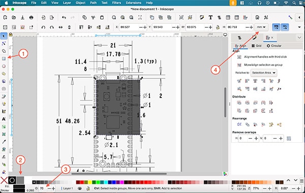 Use the highlighted UI elements to create a box (1), set its fill color (2), adjust the opacity (3), and set the units to millimeters (4).
Then, copy the chosen values to the shape’s width and height input boxes:
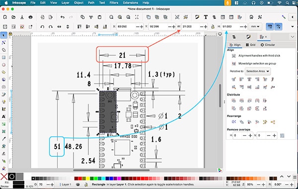 Scale the box so that it matches the values shown in the drawing
Usually, one millimeter in the drawing will not correspond to one millimeter in Inkscape. Thus, you might need to adjust the drawing size to align it with the created shape. Inkscape lets users adjust imported images by clicking on them and then using the arrows around the image. The Ctrl-key ensures that the image retains its original aspect ratio:
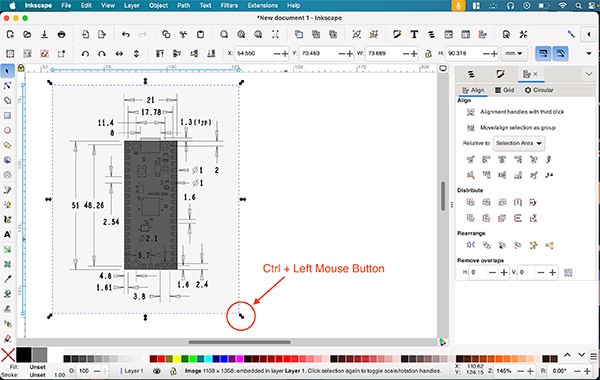 Align the image with the created shape
While this approach is not 100% accurate, it often suffices for the tolerances offered by 3D printing. However, if more accuracy is needed, you can fully recreate a vector drawing based on the measurements in the technical drawing. Naturally, doing so will take longer but also result in a perfect digital recreation within Inkscape.
Designers can easily enhance the alignment of their shapes by zooming in and selecting the shape. By holding down the Alt-key (option on Mac) and using the arrow keys on the keyboard, you can move the shape in small increments until it aligns perfectly with the drawing. This straightforward process ensures precise alignment:
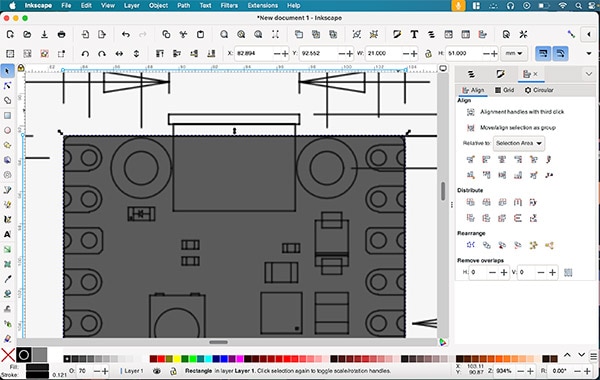 Zooming in allows for more accurate alignment
Recreating the Drawing in Inkscape
Once aligned, recreate the technical drawing in Inkscape by following the imported design template. In this case, the parts’ corners are slightly rounded. The rectangle tool allows designers to round the edges of existing shapes by using the circle that appears in the top-right corner of the black box created earlier:
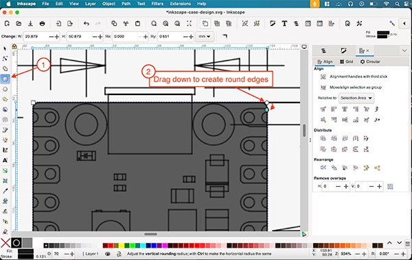 Use the circle in the top-right corner to round the rectangle’s edges
Next, create circles to cut out holes from the base shape. The technical drawing should indicate the size of the holes. In this example, all holes have a diameter of 2.1mm, which corresponds to a radius of 1.05mm in each direction:
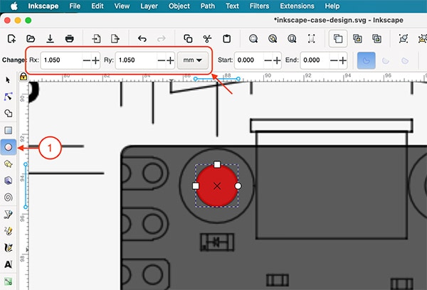 Use the highlighted UI elements to create a circle and place it in the appropriate position of the drawing.
I changed the circle’s fill color for better visibility.
Duplicate the created circle using Ctrl + D and move it to the right over the other mounting hole using the cursor tool. Holding down the control key restricts the movement to one axis to keep the duplicated shape aligned with the first hole. Repeat these steps to create four circles that are aligned with the drawing’s holes:
 This screenshot shows the aligned circles.
Then, select all four circles using the mouse while holding down the shift key. Once selected, use the combine option (Ctrl + K) located in the path menu:
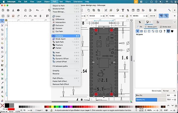 Combine paths by using Inkscape’s main menu bar
The next step is cutting out the circles from the base shape using Inkscape’s path menu. Select the rectangle and then the circle group using the mouse while holding down the shift key, and choose the difference option from the path menu:
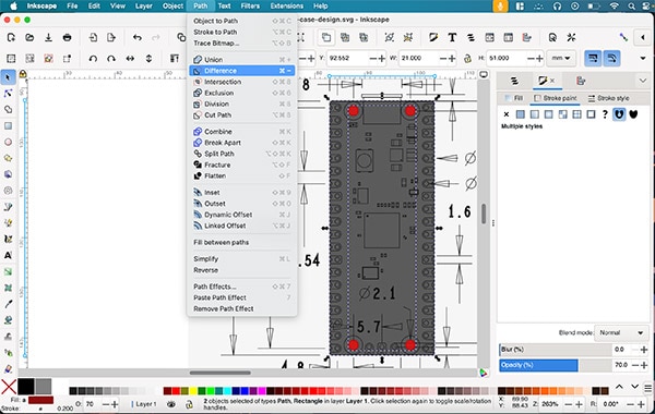 This image shows the selected shapes and the highlighted difference option in the main menu bar.
Duplicate the resulting shape and move it aside for later use. Then, create a small box for the USB port located at the top edge of the board and repeat the steps from before to make a cutout that’s slightly larger than the connector on the technical drawing:
 Repeat the steps from before to create a rectangular cutout in the USB socket’s location.
The resulting piece will act as the center of a three-piece case. Therefore, the next step involves removing the middle part of the black rectangle. Create a new rectangle that comfortably fits within the main shape. Place it roughly in the center of the main part. Then, select the original shape and the new rectangle and use Inkscape’s align and distribute tools to center the smaller shape within the larger object:
 Use the align and distribute tool to align shapes
Then, use the difference tool to create a cutout, like before:
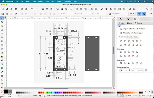 The resulting shape should look similar to this. In addition, there should be a duplicate of the PCB shape with four holes.
Exporting the Vector Shapes to a 3D Program
The last step of creating a simple case using Inkscape entails exporting the shapes to a 3D modeling program to give them depth and convert the result to a 3D-printable STL file. To do that, select one of the two shapes in Inkscape and use the export option from the file menu. In the export dialog, select SVG as the file type and tick the checkbox to export only the selected shape. Save the result on your computer’s hard drive and repeat the steps for the other shape.
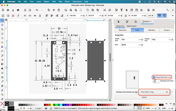 Select each of the shapes as individual SVG files
Then, import the SVG files into the 3D modeling tool of your choice. Tinkercad is a fantastic option for beginners. Regardless of the tool, extrude the shapes to the desired thickness. In this instance, I extruded the middle piece to around 3mm. I imported the other rectangular shape twice and extruded each to 2mm height. These will be the top and bottom parts of the case:
 This image shows the three-part case in Tinkercad
This example illustrates how you can create a simplistic case for a Raspberry Pi Pico using Inkscape. However, you can adapt the methods from this article to make much more intricate designs from technical drawings using Inkscape.
Have questions or comments? Continue the conversation on TechForum, DigiKey's online community and technical resource.


