制造商零件编号 5800
EVAL BOARD FOR ESP32-S3
Adafruit Industries LLC
License: See Original Project Board Specific Displays LCD / TFT Touch ESP32
Courtesy of Adafruit
Guide by M. LeBlanc-Williams
Overview
The Qualia ESP32-S3 board is capable of driving RGB 666 dot clock displays, but the code to initialize them can be a bit long and most people don't want the first 50 to 100 lines of their code dedicated to just initializing the display. You can find more information about their usage in the Adafruit Qualia ESP32-S3 for RGB-666 Displays guide.
The Qualia helper library removes a lot of the overhead work of getting the display up and running allowing you to concentrate on your project code instead of trying out a myriad of drivers, initialization codes, and timings just to get the display to show something.
It works by initializing the display as well as the appropriate touch driver if there is one for the display. The Qualia helper library is also built on top of the PortalBase library, which gives it many of the functions available to boards such as the PyPortal and MatrixPortal.
This guide will go overusing the library as well as covering the examples included with the library.
Parts
Also, compatible displays, under Featured Products or as listed under Qualia.
Create Your settings.toml File
CircuitPython works with WiFi-capable boards to enable you to make projects that have network connectivity. This means working with various passwords and API keys. As of CircuitPython 8, there is support for a settings.toml file. This is a file that is stored on your CIRCUITPY drive, which contains all of your secret network information, such as your SSID, SSID password and any API keys for IoT services. It is designed to separate your sensitive information from your code.py file so you are able to share your code without sharing your credentials.
CircuitPython previously used a secrets.py file for this purpose. The settings.toml file is quite similar.
Your settings.toml file should be stored in the main directory of your CIRCUITPY drive. It should not be in a folder.
CircuitPython settings.toml File
This section will provide a couple of examples of what your settings.toml file should look like, specifically for CircuitPython WiFi projects in general.
The most minimal settings.toml file must contain your WiFi SSID and password, as that is the minimum required to connect to WiFi. Copy this example, paste it into your settings.toml, and update:
your_wifi_ssid
your_wifi_password
CIRCUITPY_WIFI_SSID = "your_wifi_ssid"
CIRCUITPY_WIFI_PASSWORD = "your_wifi_password"
Many CircuitPython network-connected projects on the Adafruit Learn System involve using Adafruit IO. For these projects, you must also include your Adafruit IO username and key. Copy the following example, paste it into your settings.toml file, and update:
your_wifi_ssid
your_wifi_password
your_aio_username
your_aio_key
CIRCUITPY_WIFI_SSID = "your_wifi_ssid"
CIRCUITPY_WIFI_PASSWORD = "your_wifi_password"
ADAFRUIT_AIO_USERNAME = "your_aio_username"
ADAFRUIT_AIO_KEY = "your_aio_key"
Some projects use different variable names for the entries in the settings.toml file. For example, a project might use ADAFRUIT_AIO_ID in the place of ADAFRUIT_AIO_USERNAME. If you run into connectivity issues, one of the first things to check is that the names in the settings.toml file match the names in the code.
Not every project uses the same variable name for each entry in the settings.toml file! Always verify it matches the code.
settings.toml File Tips
Here is an example settings.toml file.
# Comments are supported
CIRCUITPY_WIFI_SSID = "guest wifi"
CIRCUITPY_WIFI_PASSWORD = "guessable"
CIRCUITPY_WEB_API_PORT = 80
CIRCUITPY_WEB_API_PASSWORD = "passw0rd"
test_variable = "this is a test"
thumbs_up = "\U0001f44d"
In a settings.toml file, it's important to keep these factors in mind:
Strings are wrapped in double quotes; ex: "your-string-here"
Integers are not quoted and may be written in decimal with optional sign (+1, -1, 1000) or hexadecimal (0xabcd).
Use \u escapes for weird characters, \x and \ooo escapes are not available in .toml files
Unicode emoji, and non-ASCII characters, stand for themselves as long as you're careful to save in "UTF-8 without BOM" format
When your settings.toml file is ready, you can save it in your text editor with the .toml extension.
Accessing Your settings.toml Information in code.py
In your code.py file, you'll need to import the os library to access the settings.toml file. Your settings are accessed with the os.getenv() function. You'll pass your settings entry to the function to import it into the code.py file.
import os

print(os.getenv("test_variable"))
In the upcoming CircuitPython WiFi examples, you'll see how the settings.toml file is used for connecting to your SSID and accessing your API keys.
Usage
Choosing your layers is an important part of creating a project with regards to the Portal-style libraries since it's easy to accidentally choose layers that end up duplicating some of the functions. This guide is intended to help clarify your understanding of the layout so you can make the best choices for your needs.
The PyPortal library, which is what inspired this library was written as a single layer which had the advantage of making it really simple to use for a certain type of project and it worked well for the PyPortal because the hardware setup varies very little between the different models. As more boards were written in this style of library, a base library called PortalBase was created to make it easier to maintain multiple libraries. The libraries were originally broken up into layers to allow for loading only the parts that were needed for a project with the advantage of saving memory when there wasn't much to spare.
For the Qualia ESP32-S3, there is plenty of PSRAM available, so you could just load the topmost layer. However, with continuing the tradition of layers and the fact that some of the huge displays can take up a good chunk of the RAM, not loading more than needed is still a good approach.
Mixing and Matching Layers
Which of the layers you choose to use for your project depends on the amount of customization and memory management you would like in your project. The higher level up you go in the library layer hierarchy, the more automatic functions you will have available to you, but it also takes away your ability to customize things and uses more memory.
In general, you will likely want at least one of the Graphics layers and optionally one of the Network layers. If you plan on using the peripherals specific to the board such as the buttons, you will want the peripherals layer as well.
Graphics Layers
For the Qualia library having multiple possible displays, a slightly different approach was taken with writing Graphics layers. There is a folder of displays that contain both the DotClockDisplay base class and the display-specific classes.
There is also a Displays class, which can be found alongside the Graphics class that was written for the purpose of finding all of the display-specific classes and loading the filename as an attribute in all uppercase. This class has only static functions because it is meant to be used without instantiating it first.
This makes it easy to add new displays to the library since everything is just kept in one place.
Network Layers
On the network functionality side of things, you will want to include the Network layer, which includes some convenient functions such as fetch for data and wget for downloading files. With plenty of RAM, the Qualia should be able to handle most downloads.
Peripherals Layer
To use the peripheral functionality, if you just wanted to initialize the buttons or control the display's backlight, then you would want to use the Peripherals layer. Compared to some of the other Portal-style boards, the Qualia ESP32-S3 has very few peripherals.
Top Layer
If you wanted everything along with some great functionality that ties all the legs of the hierarchy together then you would want the very top layer, which is the Qualia layer. This layer is the all-inclusive layer. To access the lower layers, you can use the following attributes:
peripherals - The Peripherals Layer
graphics - The Graphics Layer
network - The Network Layer
display - The FrameBufferDisplay layer
graphics.dotclockdisplay - The DotClockDisplay layer
Remember that if you go with this layer, you should not import any of the lower layers with the exception of the Displays layer.
Importing your layers
Displays Layer
This layer is special since it will automatically enumerate the displays upon import, and you will need it in order to instantiate the Top or Graphics layers
from adafruit_qualia.graphics import Displays
To refer to a specific display, you would refer to it starting with Displays. followed by the filename in all capital letters without the .py at the end. For example:
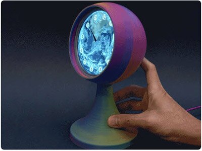
Displays.ROUND21 - Round 2.1" Display
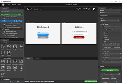
Displays.SQUARE34 - Square 3.4" Display
Displays.BAR320X820 - 320x820 Bar Display
These are only a few of the supported displays. Check the displays folder for a complete list of available displays. It doesn't matter whether your display has touch or not as it will attempt to initialize the appropriate touch driver, but if the chip isn't found, it will still load.
Alternatively, you could just use a string with the filename in all lowercase without the .py extension. For example, "round21".
Top Layer
To import the top-level layer only, you would simply just import it like this:
from adafruit_qualia import Qualia
If you would like access to the lower layers, you can directly access them as attributes. For instance, if you instantiated the top layer as qualia, then you could access the layers.
qualia = Qualia(DISPLAY)
network = qualia.network
graphics = qualia.graphics
peripherals = qualia.peripherals
Replace with DISPLAY with the display you have connected such as Displays.ROUND21. See the Displays Layer for more information.
If you would prefer, you don't even need to assign them to variable and can just directly access the attributes when needed.
Sub-Layers
To only import sub-layers such as the Graphics and Network layers, you would import it like this:
from adafruit_qualia.graphics import Graphics
from adafruit_qualia.network import Network
After they're imported, you would just instantiate each of the classes separately.
graphics = Graphics(DISPLAY)
network = Network()
Replace with DISPLAY with the display you have connected such as Displays.ROUND21. See the Displays Layer for more information.
Code Examples
Here is the code from one of the examples that are included with the library. To run the examples, simply rename them as code.py and place them in the root of your CIRCUITPY drive.
Simple Test
This example was written to use the square 3.4" display, but should be able to work with any of the displays. It uses the top-level Qualia layer and makes use of the graphics and network. It connects to your WiFi, downloads some test data, and displays the data in the REPL.
# SPDX-FileCopyrightText: 2023 Melissa LeBlanc-Williams for Adafruit Industries
#
# SPDX-License-Identifier: Unlicense
#
# NOTE: Make sure you've set up your settings.toml file before running this example
# https://learn.adafruit.com/getting-started-with-web-workflow-using-the-code-editor/

from adafruit_qualia import Qualia
from adafruit_qualia.graphics import Displays

# Set a data source URL
TEXT_URL = "http://wifitest.adafruit.com/testwifi/index.html"

# Create the Qualia object
qualia = Qualia(Displays.SQUARE34, url=TEXT_URL)

# Go get that data
print("Fetching text from", TEXT_URL)
data = qualia.fetch()

# Print out what we got
print("-" * 40)
print(data)
print("-" * 40)
Quotes Example
The quotes example is more like how the PyPortal works in that a data source is defined, two text fields are created, and the quote and author data are displayed. This example was also written for the square 3.4" display but could be modified to run on other displays by adjusting the text field settings such as text_wrap.
# SPDX-FileCopyrightText: 2019 Limor Fried for Adafruit Industries
# SPDX-FileCopyrightText: 2023 Melissa LeBlanc-Williams for Adafruit Industries
#
# SPDX-License-Identifier: MIT

import time
from adafruit_qualia import Qualia
from adafruit_qualia.graphics import Displays

# Set up where we'll be fetching data from
DATA_SOURCE = "https://www.adafruit.com/api/quotes.php"
QUOTE_LOCATION = [0, "text"]
AUTHOR_LOCATION = [0, "author"]

qualia = Qualia(
    Displays.SQUARE34,
    url=DATA_SOURCE,
    json_path=(QUOTE_LOCATION, AUTHOR_LOCATION),
    default_bg=0x333333,
)

qualia.add_text(
    text_position=(20, 120),  # quote location
    text_color=0xFFFFFF,  # quote text color
    text_wrap=25,  # characters to wrap for quote
    text_maxlen=180,  # max text size for quote
    text_scale=3,  # quote text size
)

qualia.add_text(
    text_position=(5, 240),  # author location
    text_color=0x8080FF,  # author text color
    text_wrap=0,  # no wrap for author
    text_maxlen=180,  # max text size for quote & author
    text_scale=3,  # author text size
)

while True:
    try:
        value = qualia.fetch()
        print("Response is", value)
    except (ValueError, RuntimeError, ConnectionError, OSError) as e:
        print("Some error occured, retrying! -", e)
    time.sleep(60)
QR Code Example
The QR Code Generation example generates a QR code and displays it in the center of the display. This example was written for the round 2.1" display but could easily be adapted for the other displays.
# SPDX-FileCopyrightText: 2021 Jose David M.
# SPDX-FileCopyrightText: 2023 Melissa LeBlanc-Williams for Adafruit Industries
#
# SPDX-License-Identifier: MIT

# NOTE: Make sure you've set up your settings.toml file before running this example
# https://learn.adafruit.com/getting-started-with-web-workflow-using-the-code-editor/
"""
This example shows a web address QR on the display
"""

import time
from adafruit_qualia.graphics import Graphics, Displays
from adafruit_qualia.peripherals import Peripherals

# Background Information
base = Graphics(Displays.ROUND21, default_bg=0x990099)

# Set up Peripherals
peripherals = Peripherals(i2c_bus=base.i2c_bus)

# Set display to show
display = base.display

# WebPage to show in the QR
webpage = "http://www.adafruit.com"

# QR size Information
qr_size = 9  # Pixels
scale = 10

# Create a barcode
base.qrcode(
    webpage,
    qr_size=scale,
    x=(display.width // 2) - ((qr_size + 5) * scale),
    y=(display.height // 2) - ((qr_size + 4) * scale),
)

while True:
    if peripherals.button_up:
        peripherals.backlight = True
    if peripherals.button_down:
        peripherals.backlight = False
    time.sleep(0.1)
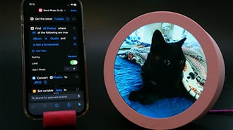
Paint Example
This last example is the most complex one and will run on any of the displays with a touchscreen. This was adapted from an example included in the FocalTouch library and ends up being around 30 lines less, but supporting many more displays. This example only uses the Graphics layer and shows how to make use of the touch screen.
# SPDX-FileCopyrightText: 2023 Melissa LeBlanc-Williams for Adafruit Industries
# SPDX-License-Identifier: MIT
"""
Simple painting demo that works with on any touch display
"""
import displayio
from adafruit_qualia.graphics import Graphics, Displays

# For other displays:
# 2.1" Round = Displays.ROUND21
# 3.4" Square = Displays.SQUARE34
# 320 x 820 Bar - Displays.BAR320X820
# 320 x 960 Bar - Displays.BAR320X960
graphics = Graphics(Displays.SQUARE40, default_bg=None, auto_refresh=False)

if graphics.touch is None:
    raise RuntimeError("This example requires a touch screen.")

# Main Program
pixel_size = 6
palette_width = 160
palette_height = graphics.display.height // 8

bitmap = displayio.Bitmap(graphics.display.width, graphics.display.height, 65535)

# Create a TileGrid to hold the bitmap
tile_grid = displayio.TileGrid(
    bitmap,
    pixel_shader=displayio.ColorConverter(input_colorspace=displayio.Colorspace.RGB565),
)

# Add the TileGrid to the Group
graphics.splash.append(tile_grid)

# Add the Group to the Display
graphics.display.root_group = graphics.splash

current_color = displayio.ColorConverter().convert(0xFFFFFF)

for i in range(palette_width):
    color_index = i * 255 // palette_width
    rgb565 = displayio.ColorConverter().convert(
        color_index | color_index << 8 | color_index << 16
    )
    r_mask = 0xF800
    g_mask = 0x07E0
    b_mask = 0x001F
    for j in range(palette_height):
        bitmap[i, j + palette_height] = rgb565 & b_mask
        bitmap[i, j + palette_height * 2] = rgb565 & (b_mask | g_mask)
        bitmap[i, j + palette_height * 3] = rgb565 & g_mask
        bitmap[i, j + palette_height * 4] = rgb565 & (r_mask | g_mask)
        bitmap[i, j + palette_height * 5] = rgb565 & r_mask
        bitmap[i, j + palette_height * 6] = rgb565 & (r_mask | b_mask)
        bitmap[i, j + palette_height * 7] = rgb565

graphics.display.auto_refresh = True

while True:
    if graphics.touch.touched:
        try:
            for touch in graphics.touch.touches:
                x = touch["x"]
                y = touch["y"]
                if (
                    not 0 <= x < graphics.display.width
                    or not 0 <= y < graphics.display.height
                ):
                    continue  # Skip out of bounds touches
                if x < palette_width:
                    current_color = bitmap[x, y]
                else:
                    for i in range(pixel_size):
                        for j in range(pixel_size):
                            x_pixel = x - (pixel_size // 2) + i
                            y_pixel = y - (pixel_size // 2) + j

                            if (
                                0 <= x_pixel < graphics.display.width
                                and 0 <= y_pixel < graphics.display.height
                            ):
                                bitmap[x_pixel, y_pixel] = current_color
        except RuntimeError:
            pass