制造商零件编号 ABX00052
ARDUINO NANO RP2040 CONNECT
Arduino

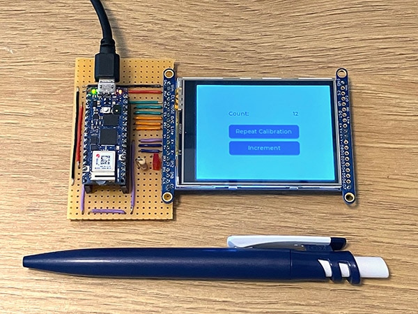
Most touchscreens are well-calibrated right out of the box. However, the detected coordinates sometimes do not match the expected values, and calibration is required to ensure that user inputs are mapped accurately. This article explains how to design and include a calibration UI in an Arduino-based project with a touchscreen.
The calibration process involves four calibration points with known positions and sizes. Users must touch each point in the correct order, and as they do so, the program registers and stores the detected positions. The program calculates how far the detected values are from the expected actual coordinates with this information. The software then adjusts all subsequent inputs to match the expected values, ensuring the best possible user experience.
The display's top-left corner should map to the coordinate system's origin. When the user clicks the top-left calibration point, the program registers the actual minimum values along both axes, which may differ significantly from (0, 0). Similarly, clicking the top-right point records the detected maximum x-position, and touching the third calibration point in the bottom-right corner stores the maximum y-value of the screen. The last point helps obtain more accurate calibration results.
Since the proper button positions and the screen size are known, the program uses the collected values from the calibration process to calculate the coordinate offset. This offset is then applied to all subsequent touch inputs to accurately determine the actual pixel position on the UI.
Previous articles discussed an embedded UI designer program called EEZ Studio, which lets you design engaging embedded graphical interfaces for touchscreen-based projects. Newcomers to UI design and LVGL should read those articles before proceeding.
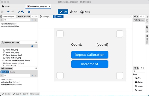
 This screenshot shows the calibration UI, the user actions, and the global variables in EEZ Studio.
This basic UI comprises two buttons, two labels, and four panels. The buttons determine whether the calibration was successful and if it needs to be repeated if the input is still inaccurate. The labels display a simple counter that you can advance using one of the buttons. The four panels act as the calibration points with a fixed location and size. Each corner has one calibration point, and each panel is ten pixels away from the borders. Finally, the calibration points are 32 pixels wide and tall.
The UI further contains two user actions, one for each button. These actions act as event handler functions that are called whenever users push the associated button. In addition to these actions, the UI also contains three global variables.
The first one represents the counter value. It is not linked to any UI elements. Instead, the Arduino handles updating the value and displaying it using the previously mentioned label. The second variable holds the calibration progress. The Arduino code must advance the variable after users click one of the calibration points. The final variable is linked to the repeat button’s hidden flag within EEZ Studio. Toggling the Boolean value of this variable turns the button visible or invisible, depending on the state.
A previous article explains the entire process of importing an EEZ Studio UI into an Arduino sketch in great detail, and the following sections assume that you are familiar with the necessary steps and that the UI is up and running at this point with the following implementations included in the vars.c file:
#include "vars.h"

int32_t count = 0;
int32_t calibrationStep = 0;
bool repeatButtonHidden = true;

int32_t get_var_count() {
    return count;
}
void set_var_count(int32_t value) {
    count = value;
}
bool get_var_hide_repeat_button() {
    return repeatButtonHidden;
}
void set_var_hide_repeat_button(bool value) {
    repeatButtonHidden = value;
}
void set_var_calibration_step(int32_t value) {
    calibrationStep = value;
}
int32_t get_var_calibration_step() {
    return calibrationStep;
}
These getter and setter methods either set or retrieve the variable's value without performing additional tasks. Similarly, the implementations of the user actions defined in EEZ studio merely call the getter and setters to manage the UI application’s state:
#include "actions.h"
#include "vars.h"

void action_repeat_button_clicked(lv_event_t * e) {
    set_var_hide_repeat_button(true);
    set_var_calibration_step(0);
}
void action_increment_button_clicked(lv_event_t * e) {
    set_var_count(get_var_count() + 1);
}
The two actions state that clicking the calibration button restarts the process by setting the calibrationStep variable to zero and hiding the repeat button. Similarly, clicking the increment button advances the counter by one. The Arduino sketch implements the actual calibration logic.
The Arduino sketch starts by importing the necessary external files and libraries. In this case, the sketch requires LVGL to draw the UI, the Adafruit Touchscreen library to detect inputs, and TFT_eSPI to communicate with the display. The standard limits.h import defines specific constant values used in the code. Additionally, the sketch imports the main ui.h and the vars.h files required for accessing UI elements and global variables:
#include <lvgl.h>
#include <limits.h>
#include <TFT_eSPI.h>
#include <ui.h>
#include "TouchScreen.h"
#include "vars.h"
The sketch then defines some local variables for storing pin numbers and the display dimensions and for managing the calibration process:
#define YP A1
#define XM A0
#define YM 4
#define XP 5

static const uint16_t screenWidth  = 320;
static const uint16_t screenHeight = 240;
static const uint8_t screenRotation = 3;
static const uint8_t offsetFromCorner = 26;

static lv_disp_draw_buf_t draw_buf;
static lv_color_t buf[ screenWidth * screenHeight / 10 ];

bool touched = false;
bool coordinatesSet = false;

int minCalibrationX = INT_MAX;
int maxCalibrationX = INT_MIN;
int minCalibrationY = INT_MAX;
int maxCalibrationY = INT_MIN;

lv_obj_t *calibrationPoints[4];
The previous section contains four variables for holding the minimum and maximum coordinates determined during calibration. The code uses these values to determine the offset from the expected touch input coordinates. In addition, the calibrationPoints array is intended to hold references to the four calibration point UI elements. These references are needed to hide and display the currently active calibration point. Finally, the offsetFromCorner variable contains information on how far the center of each calibration point is from the nearest display corner. In this case, each center point is 26 pixels away from the next corner.
Finally, the sketch contains two objects for managing the screen:
TFT_eSPI tft = TFT_eSPI(screenWidth, screenHeight);
TouchScreen ts = TouchScreen(XP, YP, XM, YM, 400);
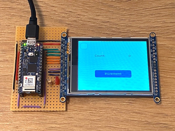
 The program starts with the top-left calibration point visible and the counter set to zero.
The Arduino sketch contains the same essential functions discussed in the previous article. The first of the four functions is the custom display flush implementation, which is the same as before:
void my_disp_flush( lv_disp_drv_t *disp, const lv_area_t *area, lv_color_t *color_p )
{
    uint32_t w = ( area->x2 - area->x1 + 1 );
    uint32_t h = ( area->y2 - area->y1 + 1 );

    tft.startWrite();
    tft.setAddrWindow(area->x1, area->y1, w, h);
    tft.pushColors((uint16_t *)&color_p->full, w * h, true);
    tft.endWrite();

    lv_disp_flush_ready(disp);
}
It sends the pixel data to the screen using TFT_eSPI. The custom touch input handler is responsible for managing the calibration process. This approach is necessary because the calibration process requires the raw touch input coordinates that are not available elsewhere in the code:
void my_touchpad_read(lv_indev_drv_t * indev_driver, lv_indev_data_t * data)
{
  TSPoint p = ts.getPoint();
  touched = (p.z > 555);

  int x = -p.y; // negate because the display is rotated
  int y = p.x;

  if(touched && !coordinatesSet)
  {
    // In calibration mode
    if (get_var_hide_repeat_button()) {
      minCalibrationX = min(minCalibrationX, x - offsetFromCorner);
      minCalibrationY = min(minCalibrationY, y - offsetFromCorner);
      maxCalibrationX = max(maxCalibrationX, x + offsetFromCorner);
      maxCalibrationY = max(maxCalibrationY, y + offsetFromCorner);
      set_var_calibration_step(get_var_calibration_step() + 1);
      if (get_var_calibration_step() > 3) {
        set_var_hide_repeat_button(false); // Calibration done!
      }
    } else {
      x = map(x, minCalibrationX, maxCalibrationX, 0, screenWidth);
      y = map(y, minCalibrationY, maxCalibrationY, 0, screenHeight);
      data->point.x = x;
      data->point.y = y;
    }

    coordinatesSet = true;
    data->state = LV_INDEV_STATE_PR;
  }

  if (!touched)
  {
    data->state = LV_INDEV_STATE_REL;
    coordinatesSet = false;
  }
}
The function starts by reading the touch point data and determining the touch strength. When the strength exceeds 555, the touched variable is set to true. If the code detects a touch input, the function checks whether the repeat button is visible. If it is hidden, the calibration is currently ongoing.
During calibration, the program records the current touch input and compares it to the previously determined minimum and maximum X and Y coordinates. It only keeps the current minima and maxima. During this process, the touch input handler does not pass on touch events to LVGL, meaning that the user cannot interact with UI elements during that time. Once done, the function advances the calibrationStep variable. When it exceeds three, the calibration process is done, and the code places the repeat button in the UI.
Once the calibration concludes, the program uses the previously recorded minima and maxima to offset each touch input and map it to a range between (0, 0) and the display’s width and height. It does that by calling the standard map function, which takes the value to map and four additional parameters. The four additional values represent the old minimum, maximum, and new range. When calibrated, the function ends by passing the state to LVGL so that the library knows that users have performed an input.
The setup method is responsible for initializing the touch screen and display driver and setting up the UI and application state:
void setup()
{
  lv_init();

  tft.begin();
  tft.setRotation(screenRotation);

  lv_disp_draw_buf_init(&draw_buf, buf, NULL, screenWidth * screenHeight / 10);

  /* Register the custom display function (omitted for brevity) */

  /* Register the touch input function (omitted for brevity) */

  // Init EEZ-Studio UI
  ui_init();

  // Assign initialized UI element pointers
  calibrationPoints[0] = objects.top_left;
  calibrationPoints[1] = objects.top_right;
  calibrationPoints[2] = objects.bottom_right;
  calibrationPoints[3] = objects.bottom_left;

  set_var_count(0);
  set_var_calibration_step(0);
  set_var_hide_repeat_button(true);
}
The last few lines of the setup method store references to the four calibration points in the previously discussed array, and the final three calls set default values for the global variables. It’s essential that the references are only set after initializing the EEZ UI to ensure that the pointer addresses are valid.
Finally, the loop function updates LVGL and the EEZ UI before hiding the currently inactive calibration points by calling a helper function, and it also updates the counter label in each iteration:
void loop() {
  lv_timer_handler();
  ui_tick();
  if (get_var_hide_repeat_button()) {
    hideInactiveCalibrationPoints();
  }
  lv_label_set_text_fmt(objects.count_value_label, "%i", get_var_count());
}

void hideInactiveCalibrationPoints() {
  for (int i = 0; i < 4; i++) {
    if (i == get_var_calibration_step()) {
      lv_obj_clear_flag(calibrationPoints[i], LV_OBJ_FLAG_HIDDEN);
    } else {
      lv_obj_add_flag(calibrationPoints[i], LV_OBJ_FLAG_HIDDEN);
    }
  }
}
The helper method iterates the previously stored references and hides all objects whose position in the array does not match the currently active calibration step.
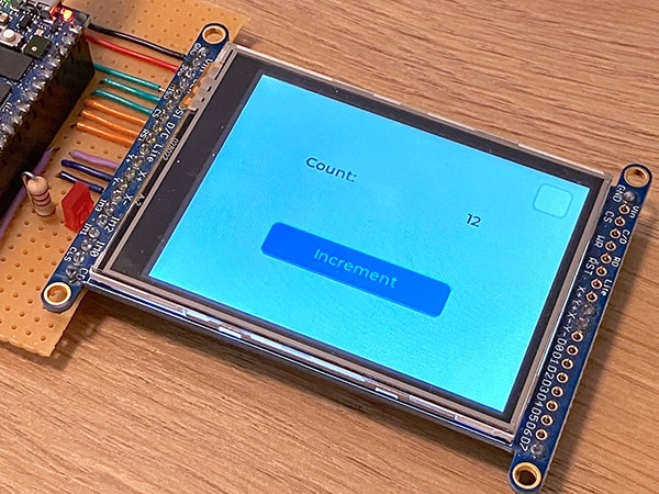
Some touchscreens require calibration to ensure accurate user input detection. During calibration, you must touch one of four calibration points in the correct order. The software records the maximum and minimum coordinates along both axes. As the actual location and size of the calibration points are known, the program can use the recorded values to calculate offsets. It then applies these offsets to all subsequent inputs to ensure accurate touch coordinate detection.
 You can repeat the calibration process by clicking the repeat button. Doing so does not reset the counter.
This article utilizes EEZ Studio to build an engaging demo UI with a calibration feature. Most of the code is similar to the one in the previous article that discusses the general steps of importing an EEZ Studio UI into an Arduino sketch. However, the touch input handler differs, as it is now responsible for calibration, as the process relies on raw touch input coordinates not available elsewhere.