制造商零件编号 A000066
ARDUINO UNO R3 ATMEGA328P BOARD
Arduino
Membrane control panels are a common sight in industrial devices and home appliances. They typically comprise an array of small tactile buttons beneath a plastic cover that contains labels that describe the functions. Besides their low mass-production cost and ease of use, these panels allow the use of devices, even with gloves. In addition, these membrane button panels are typically also water- and dust-resistant. In this article, I show how you can use a resistive touch overlay with an Arduino to build a custom touch panel for your projects. This homemade solution doesn’t include any mechanical parts, and you can easily swap out the labels to accommodate for changes in your project.
Most resistive touch overlays come with a permanently attached flexible ribbon cable that lets you connect them to a control circuit. However, official Arduino boards don’t have a matching socket you could use to connect a resistive touch overlay. Therefore, you’ll have to use a small breakout board that converts the pins of the flat flexible ribbon cable to a standard male pin header:
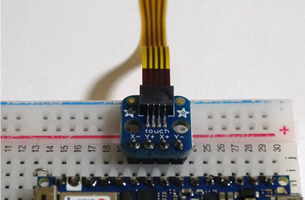 Use a small breakout adapter board to attach the flex ribbon cable to a conventional Arduino.
Next, you can use jumper wires or a breadboard with a breadboard-compatible Arduino such as the Arduino Nano 33 IoT to connect the breakout board to any four analog pins on the Arduino:
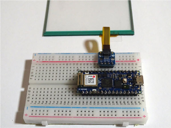 You can use a variety of Arduino boards for this project: for example, the Nano 33 IoT or the classic Arduino UNO.
Alternatively, you can also plug the adapter board directly into four analog pins on an Arduino UNO board:
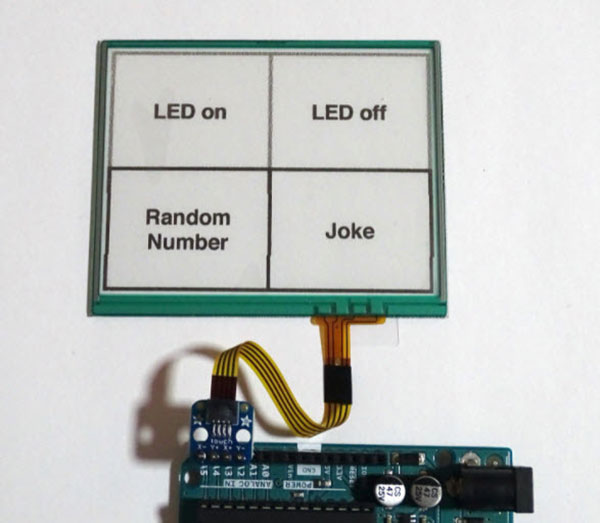 When using an Arduino UNO, you can directly plug the breakout adapter into any four analog pins of the development board.
Note that you only have to connect Y- and X- to analog pins. You may connect Y+ and X+ to either analog or digital inputs, but I have attached all four pins to analog inputs on the Arduino, as doing so made the breakout board easier to hook up.
Next, I used a simple drawing application to create a simple touch-button layout I could slide under the resistive overlay. You should, however, carefully measure the width and the height of the overlay before you draw the buttons. In this case, the display measured 2.88” by 2.17” (73mm by 55mm). I made a simple drawing that comprises four large buttons. Next, I printed the layout and attached it to the underside of the resistive overlay using two easily removable strips of double-sided tape:
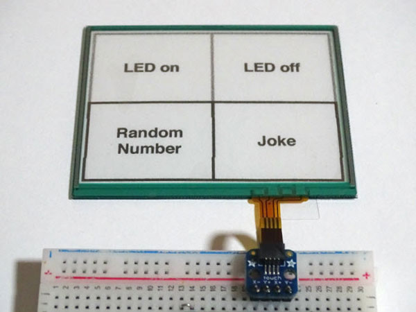 Use a drawing program to create a few buttons and slide a printed version of your design under the resistive touch overlay.
Once you’ve connected the resistive touch overlay to your development board, it’s time to make the Arduino detect user inputs. Start by using the Arduino IDE’s built-in library manager to install the ‘Adafruit Touchscreen’ library:
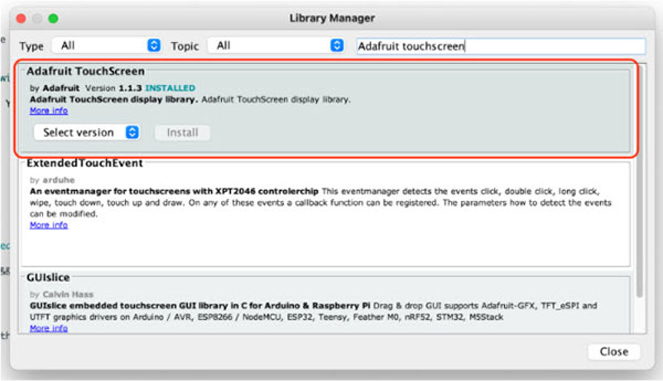 Install the highlighted package using the Arduino IDE library manager.
The following short Arduino sketch detects touch inputs using the four-button layout presented above. First, I included the Adafruit touchscreen library, and I also created a few define statements that tell the Arduino which analog ports I connected to the touchscreen. Change these pins if you use different pins. Next, the setup method initializes the serial console and the built-in LED:
#include <stdint.h>
#include "TouchScreen.h"

#define YP A4  // must be an analog pin
#define XM A5  // must be an analog pin
#define YM A2   // can be a digital pin
#define XP A3   // can be a digital pin
#define RES 300 // resistance between the X+ and X- pins
#define PRESSURE_THRESHOLD 50
#define PRESSURE_DELAY 125
#define JOKE "What's a horse's favorite wine? Chardon-Neigh"

TouchScreen ts = TouchScreen(XP, YP, XM, YM, RES);

bool fingerDown = false;
long lastTouch = 0L;

void setup()
{
  Serial.begin(9600);
  pinMode(LED_BUILTIN, OUTPUT);
}
Next, I added a small helper method to check whether the detected touch input falls within a given set of coordinates. That way, I can effortlessly check which button the user pressed:
bool touchedWithin(TSPoint touch, unsigned x, unsigned y, unsigned w, unsigned h)
{
  return (touch.x > x) && (touch.x < w) && (touch.y > y) && (touch.y < h);
}
The loop()-function calls this helper method. But first, it checks whether enough time has elapsed since it last detected an input. I’ve included this check as a de-bounce measure to reduce the number of falsely detected inputs. In addition, the loop method checks how strong a user pressed down on the overlay. The Arduino only acknowledges an input as valid if that value exceeds a predefined threshold.
If an input is valid, the program checks the coordinates at which it detected user input, and the Arduino then performs the desired action. The fingerDown variable ensures the program detects each press only once, and it ignores further inputs until the user raises their finger:
void loop()
{
  // Determine whether the user touched the display
  TSPoint p = ts.getPoint();
  long currentMillis = millis();

  if(currentMillis - lastTouch < PRESSURE_DELAY)
	return;

  if (p.z > PRESSURE_THRESHOLD)
  {
	if(!fingerDown)
	{
  	if(touchedWithin(p, 0, 0, 500, 500))           	// Bottom left button
    	Serial.println(random(1,101));
  	else if(touchedWithin(p, 500, 0, 1000, 500))   	// Top left button
    	digitalWrite(LED_BUILTIN, HIGH);
  	else if(touchedWithin(p, 0, 500, 500, 1000))   	// Bottom right button
    	Serial.println(JOKE);
  	else if(touchedWithin(p, 500, 500, 1000, 1000))	// Top right button
    	digitalWrite(LED_BUILTIN, LOW);
	}

	fingerDown = true;
	lastTouch = currentMillis;
  }
  else
  {
	fingerDown = false;                               	// Button released
  }
}
A Resistive touch overlay offers an intuitive way for users to interact with your project. You can customize the number and layout of buttons to accommodate your specific project requirements. Resistive touch overlays typically require two digital and two analog pins to communicate with a controller, such as an Arduino board. In this article, however, I connected the resistive overlay to four analog pins with the help of an adapter breakout board. The software periodically checks whether the touch overlay detected an input. If the detected touch input is significant, the Arduino triggers an action according to the coordinates.