制造商零件编号 ABX00053
ARDUINO NANO RP2040 CONNECT HDRS
Arduino
Another article explored Squareline Studio, a straightforward WYSIWYG (what you see is what you get) graphical UI editor for creating stunning user interfaces for various embedded, mobile, and desktop-based platforms. This article will take one step further, as it explains how you can export the LVGL-based designs from Squareline to any supported Arduino development board and TFT display for use in your embedded projects.
As the exported designs are based on the popular open-source LVGL package, the Arduino board chosen for UI display must meet the library’s minimum requirements. As stated in the official documentation, these requirements are a minimum of 64 kB of ROM space, 2 kB of SRAM, 2 kB of stack memory, and 2 kB of heap memory. However, these are the bare minimum requirements, and choosing a controller with more RAM and ROM space is recommended, particularly for more complex UIs. Aside from this, virtually any 16, 32, or 64-bit MCU with a clock speed of more than 16MHz will accomplish the job. This article uses an Arduino Nano RP2040 Connect, but most ESP32-based boards should also be a good choice.
Regarding the display, LVGL uses the popular TFT-eSPI library for Arduino that supports the most common TFT display driver chips you will find, including, for example, the ILI9341 found in this touchscreen display.
When creating a new project, Squareline Studio lets users pick the target platform from a list of available options. The tool also allows you to adjust the project's resolution, rotation, and color depth. You can, however, change any of these settings during development, such as when testing whether your UI scales properly or before exporting your project, as is the case here.
Use Squareline Studio’s main menu bar to open up the project preferences, then review the settings, as shown in the following screenshot:
s Open the preferences using Squareline’s file menu.
The display properties must match the target display’s resolution, as using incorrect values leads to the display library not initializing the TFT screen properly, which results in difficult-to-debug problems. In addition, color depths below 16 bits would not function correctly on my display. These settings may vary depending on the hardware in use.
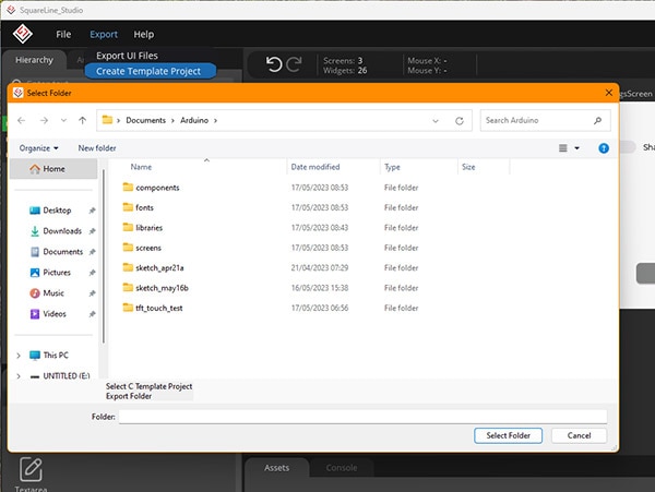
Once the settings are correct, use the export menu in Squareline Studio to create a template project and select where to store the project. In this example, I chose the main Arduino folder:
 Choose an export location for the project.
This export option creates a new Arduino sketchbook root with a custom libraries folder. While this might seem unnecessary at first, it spares programmers from the tedious task of installing libraries and moving source files around. Squareline Studio automatically includes the necessary libraries and configuration files in the new libraries folder. Further, it places all UI source files in the same folder and creates a new Arduino project called ui. Use the same menu within Squareline Studio and select the “Export UI” option to export the UI files into the chosen folder. The editor remembers the sketchbook root, and whenever changing anything in the UI, users only need to export the UI without creating a new template project.
Yet as this approach creates a custom sketchbook root, you will have to change the Arduino IDE’s sketchbook location to match the newly created project folder:
 Make sure to update the sketchbook location in the Arduino IDE.
Failing to do so will lead to multiple problems, including the IDE not finding the UI project’s source files and libraries. You should also re-download any libraries your custom project might need and place them in the newly created libraries folder.
Finally, it’s time to hook up the display to the Arduino and configure the display parameters in the TFT_eSPI library’s source files. Unfortunately, these steps heavily depend on the screen and microcontroller in use, and no universal method matches all possible combinations. However, there are a few details to keep in mind.
First, begin by connecting the display to the development board. You can follow a standardized guide, such as this one, but make sure to connect the display to the appropriate SPI pins of your development board. In the case of the Nano RP2040 Connect, those pins are:

Next, navigate to the previously created new project folder’s library folder. Then, open the TFT_eSPI subfolder and find the header file named User_Setup:
 Edit the highlighted file located in the new project root’s library folder.
Open that file using any text editor and change the pin definitions so that the particular ones in the file match the pins you choose to connect to the display. You can use the following example configuration for the Arduino Nano RP2040 Connect:
#define USER_SETUP_ID 62
#define ILI9341_DRIVER

#ifdef ARDUINO_ARCH_MBED
  #define TFT_MISO   p4
  #define TFT_MOSI   p7
  #define TFT_SCLK   p6
  #define TFT_CS     p5
  #define TFT_DC    p20
  #define TFT_RST   p21
  #define TOUCH_CS  p19
#else
  #define TFT_MISO  D12
  #define TFT_MOSI  D11
  #define TFT_SCLK  D13
  #define TFT_CS    D10
  #define TFT_DC    D8
  #define TFT_RST   D9
  #define TOUCH_CS  D7
#endif

#define LOAD_GLCD
#define LOAD_FONT2
#define LOAD_FONT4
#define LOAD_FONT6
#define LOAD_FONT7
#define LOAD_FONT8
#define LOAD_GFXFF
#define SMOOTH_FONT

#define SPI_FREQUENCY  20000000
#define SPI_READ_FREQUENCY  20000000
#define SPI_TOUCH_FREQUENCY  2500000
Please note that this configuration highly depends on the display and board. When using another display controller IC, you must also adjust the driver definition in that file to match the controller. Further, CS, DC, and RST may connect to any digital I/O pin on the microcontroller. In these particular instances, you’ll then have to also adjust the pin numbers accordingly.
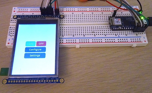
Once done, open the ui Arduino project file in the folder with the same name within the sketchbook root folder created earlier. The project should compile and upload to a supported board without errors. Once done, the display shows the previously created UI:
 The UI shows up on the display. Note that this picture omits the touchscreen wires.
You can export a Squareline Studio UI project to a microcontroller, such as an Arduino-compatible development board, in just a few minutes to build magnificent embedded graphical HMIs.
The process starts with exporting a template project from within Squareline Studio. While this step is not strictly necessary, it saves a few clicks, as it includes all required libraries and configuration files, you’d otherwise have to install yourself. However, this convenience feature requires setting the Arduino IDE’s sketch folder to the newly created template project.
Finally, you have to adjust the settings in the TFT_eSPI library’s config file to match their setup. Changing the pin numbers according to their wiring typically suffices. This isn’t always the case though, and certain displays may require a different driver to be loaded or additional options to be set. It’s best to refer to the datasheet of your display or development board for further information.