制造商零件编号 4600
QT PY SAMD21 WITH STEMMA QT
Adafruit Industries LLC
Welcome to another teardown! This time we’re taking a look at the CurrentBody LED red light therapy mask. In this article, you’ll see me try it out, take it apart, and analyze the design and manufacturing of the circuitry inside. I also tried to see if I could figure out how much it would cost to make my own.
My friend Michelle from Lab Muffin Beauty Science sent me this mask. It’s basically a flat, flexible LED panel meant to be worn on your face. It’s got a long USB cable that connects to the battery pack.
See, Michelle, my other friend Ruth Amos, and I are all very curious about these devices. How do they work, and what’s the science backing up the marketing claims? Is it really worth the $400 price tag? Could we make a DIY version? We all got on the horn to talk about it. Be sure to check out my video above, as well as Michelle’s video for the science of how red-light therapy masks work, and Ruth’s video where she DIYs her own. This is a collab across three continents.

We figured it would be useful to be able to evaluate and test the products and components to compare notes, but it turns out spectrometers are expensive. So, I set about building a simple Arduino circuit that spits out the values from a light sensor to the serial monitor. It’s not super precise, like, the buckets of wavelengths are big, so I don’t really know if Michelle will find it useful for science purposes, but it’s worth a try.
Parts:

I could tell the difference between the readings of the mask LEDs and a plain red LED, for instance, verifying the presence of some near IR.

I used Tinkercad to make this part that holds the light sensor circuit, and 3D printed it on my Bambu printer. You can find the file on the Tinkercad site.

I plugged the sensor into the microcontroller board with a small wire connector. The code is one of the examples that comes with the sensor Arduino library.

To access the bare electronics inside the mask, I cut open the clear plastic cover. Inside, there was another white plastic piece that covered up the circuit board. Freed from its silicone cage, it was easier to see the two-color LEDs on the flex PCB inside.
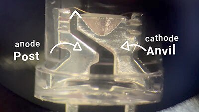
We discovered that the circuit consists of 5050 LED packages, but with only two LEDs inside, and two resistors per bi-color LED. A very simple circuit!

To me, the next logical step was to try to replicate this product’s circuit board in my PCB design software and get a quote from a manufacturer to find out the price. I scanned the mask, traced the outline in Illustrator, and saved the drawing as an SVG. In Fusion, I was able to import the SVG as a board outline.
You’ve seen me do this before in my PlayStation 4 controller breakout board project. Then I drew out a simple circuit where every LED is wired in parallel and has its own resistor.
I found a few LEDs that have one red and one infrared LED, and they are about the right wavelengths. Good enough for a quote, at least. The other option would be to use separate red and infrared LEDs.

I positioned the LEDs where they are on the commercial mask, then added a few extra, to be honest. I routed the board and added a layer that specified where the stiffeners should be, basically behind every area there are components.
Then I exported the Gerber file which contains the board specifications and created a bill of materials, or BOM, and component placement list, or CPL. These two files specify which components to use and how to orient them on the board.
Along with the settings for board thickness, etcetera, this is all you need to see how much it would cost to get these made. Many manufacturers have a minimum order quantity of five pieces, and the total price quote I got, including shipping, was just under $300. So, if you and four friends each go in together, they’d each be $60. That’s before the battery and strap situation, but still a lot cheaper than the retail price.
I didn’t actually get these made, but honestly just quoting it out was really useful in understanding what goes into this product.