Introduction to Impedance Matching
2024-10-07 | By Antonio Velasco
Within the world of consumer electronics and electrical engineering, there are a great deal of design choices that contribute towards efficiency and reliability. An example of these design choices that makes today's technology possible is impedance matching. We'll go over what it is, why it's implemented, and how it's done in modern circuits.
What's Impedance Matching?
Impedance matching is as its name suggests: ensuring that the impedance of a source is equal to the impedance of the load that it is supplying energy to. This concept is mainly used for one of two purposes: maximum power transfer, or signal loss/prevention.
How Does It Work?
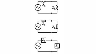
In DC circuits, there is no inductance or capacitance, so simply the impedance just needs to equal that of the resistors. This fulfills the Maximum Power Theorem, in which when the load impedance is equivalent to the source impedance, the maximum power is transmitted to the load. We can prove that theorem with the following. Let's consider this circuit:

Where let's say RL is the load resistor (impedance), and Rin is the source resistor (impedance)
Using the power equation P = I^2/R, we can prove that the maximum power output is when RL = Rin.
P = I^2/RL, where I= Vin/Rin + RL
P = (Vin/(Rin+RL))^2 * RL
P = Vin^2 * (RL/(Rin+RL)^2)
Now, to find the point at which the power is the maximum, we need to find when the derivative is equivalent to 0. As such,
dP/dR = Vin^2 (((Rin+RL)^2 * 1-RL * 2Rin + RL)) / (Rin + RL)^4)
(Rin+RL)^2 - 2RL(Rin+RL) = 0
(Rin+RL)(RL+Rin-2RL) = 0
Rin-RL = 0
Rin = RL, when dP/dR = 0
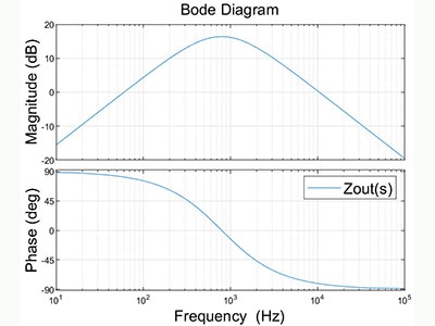
As such, maximum power is found when Rin (source impedance) is equivalent to RL (load impedance). This is depicted in the shown graph:

AC circuits differ because of the alternating direction of current, and as such consider inductance and capacitance. For these circuits, to achieve maximum power transfer, the same property of matching the impedances holds up, except with the complex portion. This is represented by Zs (source impedance) = RL (load resistance) + jXLi (complex component), or simply Zs = ZL.
In AC circuits, we can also utilize the complex conjugate of the load impedance (Zs = RL - jXLi) instead for a different purpose. This is done instead for signal loss in RF applications. Essentially, the goal here is to optimize the Voltage Standing Wave Ratio (VSWR) and ensure that the load absorbs all power. If this isn't done, there tends to be a reflection of the non-absorbed power, which can disrupt RF signal integrity and quality. This cancels out as the reactive components (inductors and capacitors) with a complex component cancel out. This preserves the signal integrity and allows for reliable RF connections.
Implementations of Impedance Matching
Impedance matching can be implemented in numerous ways, but the most obvious way is to include an impedance-matching component for the circuit. This essentially entails adding a single resistor or other capacitive/inductive components in order to match the impedance of the load. Quarter-wave transformers, stub tuners, and baluns could also be used in order to accurately balance the impedances.
Maximum power transfer is especially important in power transmission, where energy companies must lose as little power as possible. This is also present in power supplies, to ensure no electricity is wasted in the process of charging or powering a device. Efficiency is key in today's economy.
Maintaining signal integrity is crucial in every application where communication is used. Whether it's antennas, HDMI cables, or even speakers, it's important to keep out noise, which complex conjugate impedance matching does.
Overall, impedance matching is an important concept and serves to ensure that today's technologies remain reliable and efficient.