Arduino-Based Connected TODO Box
2024-10-22 | By Maker.io Staff
License: General Public License 3D Printing Switches Thermal Imaging Arduino
Keeping track of daily tasks and chores can be challenging, especially when new ones appear unexpectedly. The device I created offers a solution. Its web-based interface and built-in thermal printer allow you to organize daily chores and generate portable lists—perfect for creating a shopping list or remembering chores on the go.
Project Components
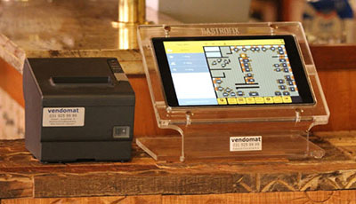
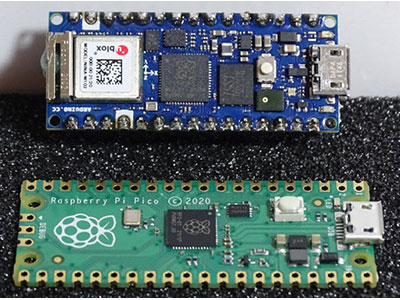
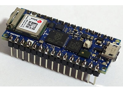
Building this project requires only a few electronic components, as the connected MCU board handles most tasks through software. This project uses an Arduino Nano RP2040 Connect, but it is possible to substitute any similar device, like an ESP8266, if you need to meet specific requirements. The project further utilizes a thermal printer to generate physical copies of the currently open tasks. A physical button starts the print. Finally, a custom 3D-printed enclosure houses all the components.
Quantity Part
1 Thermal printer
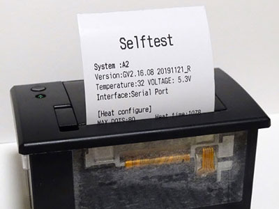
Before starting this build, you should familiarize yourself with the basics of thermal printers and how to make an Arduino communicate with standard serial printers. After understanding thermal printers and verifying that the printer works as expected, you must connect the components to the Arduino, as shown in the following circuit diagram:
This diagram illustrates how to connect the RP2040 to the thermal printer, the push button, and the LED. Scheme-It link
Note that the push button uses the Arduino’s built-in pull-up resistor instead of an external one, which helps reduce the number of components in the build. However, the LED still needs an external current-limiting resistor. Connecting the printer to the Arduino requires only two serial communication wires.
Understanding the Firmware’s Tasks
The Arduino has to perform several tasks in this project. It must connect to a wireless network and listen for incoming client requests. Whenever it receives a request, the MCU must interpret it and determine the task the client wants to perform.
Clients can request a website that lists the open tasks, which they can use to instruct the Arduino to store a new to-do entry and remove existing ones. For that purpose, the Arduino must understand standard HTTP requests, which typically consist of three blocks. The first contains the request method, the path with optional parameters, and the protocol version. The second block includes a list of request headers for transmitting additional details to the server. The request’s final block contains the payload. While the first line is mandatory, the last two blocks may be empty. A single whitespace character separates the individual parts of a line, and each line must contain exactly one entry. The requests and responses each end with a single empty line.
This image illustrates the composition of HTTP requests and HTTP responses.
The request parsing logic is abstracted in a custom library that can be downloaded from GitHub. The library code stores the client’s request in a character buffer, converts each line to Arduino strings, and then tries to interpret the strings by looking for specific characters that characterize one of the three blocks that can be in an HTTP request.
In addition to managing HTTP requests, the firmware must also use the LED to indicate that tasks are open. Finally, the Arduino must monitor the connected push button state and print out the currently open tasks when pressed.
Installing the Required Libraries
This project’s firmware relies on external libraries that greatly help reduce the boilerplate code for handling basic tasks like button debouncing. An additional library handles communication with the thermal printer via the RP2040’s hardware serial port. Thus, the following libraries are required:
WiFiNINA
Bounce2
ButtonSuite
Adafruit Thermal Printer Library
Establishing a Network Connection and Starting the Server
Once all the libraries are installed, they can be added to the project’s firmware sketch before defining multiple variables:
#include <WiFiNINA.h>
#include <PushEventButton.h>
#include <Adafruit_Thermal.h>
#include "HttpParser.h"
#include "WiFiSecrets.h"
#include "PageContents.h"

#define LED_PIN 2
#define BTN_PIN 4
#define LED_FLASH_DELAY 1500

struct TodoTask {
  String id;
  String description;
  TodoTask(String id, String description) : id(id), description(description) {}
};

vector<TodoTask> openTasks;
unsigned int addedTasks = 0;
bool printStarted = false;
unsigned long previousMillis = 0UL;

WiFiServer server(PORT);
Adafruit_Thermal printer(&Serial1);
PushEventButton printButton(BTN_PIN, PushEventButton::CAPTUREPUSH);
Next to the external libraries, the program includes three custom header files that must be present in the same directory as the sketch. The first consists of the previously discussed HTTP parsing library; the second header file contains the WiFi network’s credentials and the port to use; and the third file contains the HTML code templates the Arduino serves clients. The subsequent three statements define the pins that connect to the push button and the LED and how long the LED flash delay should be.
The Arduino stores user-created to-do tasks in a custom data structure defined after the include-statements. Each task has an ID and a description. The program keeps track of the entries by placing them in the openTasks vector and storing the count. The other two variables manage the application state and prevent users from starting multiple print processes simultaneously.
The program then creates new objects representing the WiFiServer, the printer, and the button. The WiFiServer uses the port defined in the WiFiSecrets header file. The printer uses a reference to the RP2040’s first hardware serial port. The print button requires passing the button pin and the type of event it should detect. In this case, the object should only react to button press events, not when the button is released.
The program’s setup method then makes use of these objects to establish a WiFi connection, start the WiFiServer, initialize the serial port and printer, and set up the LED pin:
void setup() {
  int status = WL_IDLE_STATUS;
  do {
    status = WiFi.begin(SSID, PASSWORD);
    delay(2000);
  }
  while (WiFi.status() != WL_CONNECTED);

  server.begin(); // Start the server

  Serial1.begin(19200); // Initialize the serial port
  printer.begin();      // Initialize the printer

  pinMode(LED_PIN, OUTPUT);
}
Responding to Client Requests
The sketch’s main loop performs three tasks: It first determines whether a client is available and wants to communicate with the server and uses the HttpParser library to dissect the incoming HTTP request if there is one. Secondly, the method checks whether a user pressed the push button, and if they did, the program calls a helper function to print the to-do entries. Finally, the loop function also flashes the LED if there are any tasks in the openTasks vector, and it turns off the LED if the vector is empty:
void loop() {
  WiFiClient client = server.available();
  if (client && client.connected()) {
    handleClientRequest(client);
  }
  if (printButton.pushed()) {
    printOpenTasks();
  }
  if (openTasks.size() > 0) {
    toggleLED();
  } else {
    digitalWrite(LED_PIN, LOW);
  }
}
Separate helper methods perform each task to make the code more organized and easier to read. The first helper function handles incoming client requests:
void handleClientRequest(WiFiClient client) {
  HttpParser clientParser(client, 1024);
    if (clientParser.receive()) {
      if(clientParser.getMethod() == "GET") {
        if (clientParser.getPath() == "/") {
          String pageToServe = String(BASIC_PAGE);
          String openTasksTableData = fillTasksTemplate(OPEN_TASK_TABLE_ROW_TEMPLATE, &openTasks);
          pageToServe.replace("%%%_OPEN_TASK_TABLE_ROWS_%%%", openTasksTableData);
          clientParser.transmit("text/html", pageToServe);
        } else if (clientParser.getPath() == "/deleteTask.js") {
          clientParser.transmit("application/javascript", DELETE_TASK_FUNCTION);
        } else if (clientParser.getPath() == "/addTask.js") {
          clientParser.transmit("application/javascript", ADD_TASK_FUNCTION);
        } else {
          clientParser.transmit(404, "Not Found");
        }
      } else if (clientParser.getMethod() == "POST") {
        openTasks.push_back(TodoTask(String(addedTasks++), String(clientParser.getData())));
        clientParser.transmit(201, "Created");
      } else if (clientParser.getMethod() == "DELETE") {
        deleteOpenTask(clientParser.getHeader("ID"));
        clientParser.transmit(200, "OK");
      } else {
        clientParser.transmit(405, "Method Not Allowed");
      }
    }
    client.stop();
    clientParser.end();
}
In this function, the server inspects the method defined in the client’s HTTP request. If it is a GET request, the server checks the path. The server knows three valid paths: the main web interface and two helper JavaScript (JS) files. The HTML and JS code are stored in the PageContents header file. The server responds with a 404 error should a client request an unknown path.
If the client sends a POST request to any path, the server extracts the data supplied with the request and passes it to the TodoTask struct to store it in the vector of open to-do entries. The program assumes that the request data contains only the task’s description, and it assigns each task a unique ID corresponding to the number of previously added tasks.
Finally, clients can also delete previously added tasks by sending a DELETE request with the ID of the task to delete in the request header. The server uses the following helper method to find and delete a previously created task:
void deleteOpenTask(String id) {
  int toRemove = -1;
  for (int i = 0; i < openTasks.size(); i++) {
    TodoTask current = openTasks.at(i);
    if (current.id == id) {
      toRemove = i;
      break;
    }
  }
  if (toRemove != -1) {
    openTasks.erase(openTasks.begin() + toRemove);
  }
}
This method iterates over all openTasks and finds the one with the matching ID if it exists. The function only deletes an entry if it finds a match.
Printing the To-Do List
The second helper method concerns itself with sending the open tasks to the thermal printer to create a physical list that users can take with them when running errands:
void printOpenTasks(void) {
  if (!printStarted) {
    printStarted = true;
    printer.println("Today\'s Tasks");
    printer.println("----------------");
    for (int i = 0; i < openTasks.size(); i++) {
      TodoTask current = openTasks.at(i);
      printer.print("[] ");
      printer.println(current.description);
    }
    printer.println("----------------");
    printer.println("Have a nice day!");
    printer.feed(1);
    resetTasks();
    printStarted = false;
  }
}
This method first determines whether a print is ongoing to prevent multiple simultaneous processes. If no print is active, the helper sets the flag and sends a few lines of hard-coded text to the printer. It then iterates over the open tasks vector and sends each entry to the thermal printer. It concludes by outputting some additional lines of text before deleting the open tasks from the vector and resetting the printStarted flag. The helper method that resets the tasks vector looks as follows:
void resetTasks(void) {
  openTasks.clear();
  addedTasks = 0;
}
Toggling the Status LED
A third helper function toggles the device’s status LED, and it looks like this:
void toggleLED(void) {
  unsigned long currentMillis = millis();
  if (currentMillis - previousMillis >= LED_FLASH_DELAY) {
    previousMillis = currentMillis;
    digitalWrite(LED_PIN, !digitalRead(LED_PIN));
  }
}
It compares the flash delay, defined at the program's start, to the elapsed time since it last changed the LED state. If the elapsed time exceeds the delay value, the program toggles the LED and sets a new previousMillis value.
Building and Serving HTML Responses
When clients request a file from the server, the loop method discussed above must return a valid HTML website wrapped within a valid HTTP response. In this example, clients can request the website and two JavaScript files, all stored as Arduino strings in the PageContents.h file. The website contains a single table that lists the open tasks, and each entry has a corresponding delete button for removing the task. Beneath the table, users can enter a new task description and send it to the server:
This image shows the web interface hosted on the Arduino.
The Arduino must dynamically inject and remove data from the HTML page. Therefore, the HTML code contains placeholder values that start and end with three percentage characters. For example, the HTML table includes a placeholder for a template table row that represents a task. The row template itself contains three placeholder values, and it looks as follows:
String OPEN_TASK_TABLE_ROW_TEMPLATE =
"<tr>\n"
"  <td>%%%_TASK_ID_%%%</td>\n"
"  <td>%%%_TASK_DESCRIPTION_%%%</td>\n"
"  <td>\n"
"    <button onclick=\"deleteTask(%%%_TASK_ID_%%%)\">Delete</button>\n"
"  </td>\n"
"</tr>\n";
The template represents a table row (tr) with three columns (td elements). The first column contains the task ID, the second the description, and the third holds the delete button. This button calls the deleteTask function, which is defined in one of the JavaScript files.
Whenever a client requests the HTML website, the server loads the templates from the header file and replaces the placeholder values using the following helper function in the main sketch file:
String fillTasksTemplate(String templ, vector<TodoTask> *src) {
  String tableContents = "";
  for (int i = 0; i < src->size(); i++) {
    TodoTask current = src->at(i);
    String tmp = String(templ);
    tmp.replace("%%%_TASK_ID_%%%", String(current.id));
    tmp.replace("%%%_TASK_DESCRIPTION_%%%", current.description);
    tableContents = tableContents + tmp;
  }
  return tableContents;
}
This helper method loops over all entries in the vector and creates a copy of the template in each iteration. It then utilizes the default string replace function to replace each placeholder value with the actual data before the server sends the enriched HTML code to the client. Note that the remainder of the HTML code was omitted for brevity but can be downloaded at the end of the article.
Creating and Deleting Tasks
Clients must also be able to delete previously created entries by sending a DELETE request to the server, which is handled by one of the website's helper JavaScript files:
String DELETE_TASK_FUNCTION = "function deleteTask(id) {\n"
"    fetch('/', {\n"
"        method: 'DELETE',\n"
"        headers: {\n"
"            'ID': id,\n"
"        },\n"
"    })\n"
"    .then(response => {\n"
"        if (response.status === 200) {\n"
"            window.location.reload();\n"
"        }\n"
"    });\n"
"}\n";
This script sends a DELETE request to the server with the task’s ID in a custom header. If the deletion succeeds, the server responds with a status code of 200, and the script reloads the HTML page displayed in the client’s browser.
The addTask function instructs the server to create a new task. It first reads the user-entered value from the taskDescription input field. Then, it sends a POST request to the server with the new task’s description in the request body. If the server returns HTTP code 201, the script reloads the page.
String ADD_TASK_FUNCTION = "function addTask() {\n"
"    const inputField = document.querySelector('input[name=\"taskDescription\"]');\n"
"    const taskDescription = inputField.value.trim();\n"
"    if (taskDescription.length == 0) {\n"
"        return;\n"
"    }\n"
"    fetch('/', {\n"
"        method: 'POST',\n"
"        headers: {\n"
"            'Content-Type': 'text/plain',\n"
"        },\n"
"        body: taskDescription\n"
"    })\n"
"    .then(response => {\n"
"        if (response.status === 201) {\n"
"            window.location.reload();\n"
"        }\n"
"    });\n"
"}\n";
Assembling the Device
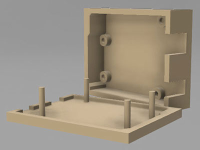
Assembly starts with downloading and printing the enclosure STL files on a 3D printer. The case comprises two parts. The printer is mounted in the top case using the screws and clamps on the thermal printer’s housing. This part also houses the push button, which snaps into place in the bigger of the two holes. The smaller one is intended for the power cable. It needs to be inserted and then secured, for example, by tying a knot in the insulated part to serve as a strain relief. After inserting the parts into the case, they must be connected electrically, as shown in the circuit diagram above.
This image shows the thermal printer and button mounted in the top half of the enclosure. The Arduino was removed for this image.
Finally, the code must be uploaded to the Arduino board before snapping the bottom piece of the enclosure into the top half. The two pieces should fit together nicely by friction alone. However, a bit of glue can create a more permanent bond.
Summary
This practical device lets you organize your daily to-do list using a simple web interface. You can then create a physical copy of the list to take with them, for example, when going out for groceries.
An Arduino Nano RP2040 Connect is the heart of this project. It opens a server, accepts incoming client requests, parses them, and responds to clients with the requested resource. For that purpose, the MCU must understand and create standard HTTP requests. The protocol is straightforward, and well-formed requests and responses comprise three blocks. In HTTP requests, the first block contains the method, path, and protocol version. In its responses, the server includes the status code and a message in the first line. This line is followed by optional headers containing further information about the request. The third block is also optional. When included, it contains the request’s actual data.
Aside from handling client requests, the project’s firmware is also responsible for flashing the device’s LED to indicate that users have unfinished tasks. It further monitors a push-button state, which starts the thermal print process when pressed.


