制造商零件编号 VDV226-005
COMPACT PASS THRU RJ45 CRIMPING
Klein Tools, Inc.
The house I live in was wired with Ethernet throughout the bedrooms and living areas. Since I wasn’t getting good Wi-Fi where my desk was, I thought I’d try hooking into one of the wall jacks to get a wired connection to my router. But it didn’t show as connected!
Searching around, I finally found a structured media enclosure in a closet, where all the CAT5E Ethernet cables (and coaxial cables) converged. I needed to put an Ethernet switch in there to link all the wall ports to my router, but none of the Ethernet cables had RJ45 connectors!
I didn’t want to call an electrician out just to crimp some connectors, so, naturally as an electrical engineer, I figured I’d learn how to add them myself. I also found out a lot about how Ethernet cables connect devices to the internet—you can find my article on that here if you’re interested!
For this article, I’ll go into how I created and tested my own cable assemblies.
I already had the cables, I just needed to be able to cut them to specific lengths, crimp on the connectors, and test them.
After some research, I ordered a Klein Tools Compact Pass-Thru™ Crimper, some Pass-Thru™ connectors, colored strain-relief boots, and an Ethernet cable tester.
I opted for the Compact Crimper because it is, as its name suggests, smaller than the regular crimper. The tradeoff is that it gives up the RJ11/12 crimper (but who uses telephone/voice landlines these days anyway?).
Step 1: There are two standards for ordering the wires in a cable – T568A and T568B. The only difference is in where the green and orange wires go. If you’re making your cables from scratch, just pick one and make sure it’s consistent on both ends of the cable. In my case, I opened up one of my wall Ethernet ports to check.
Step 2: Using a knife, scissors, or wire stripper, strip off the outer jacket from the end of the cable. I do around ¾”, but the beauty of the Pass-Thru™ style connectors is that the wire lengths don’t need to be precise – I make them longer and then the crimper will trim off any excess.
Step 3: This is optional, but I put on a strain relief boot, which also helps to color-code my cables.

Step 4: Untwist the individual wires, then rearrange them in the T568A or T568B standard.

Step 5: Insert the wires into the Pass-Thru™ connector and in the crimper. Before crimping, verify the order of the wire colors. The crimper has a handy sticker with the two conventions.

Step 6: Crimp the connector. The blade on the crimper will also trim off the excess wire.

Step 7: After the connector is crimped, you can use an Ethernet tester to verify that it was done properly. Ethernet testers typically come in two parts – one for each end of the cable. In my case, one side needed to go to the existing port in my wall.

An Ethernet tester isn’t needed, but it makes it easier to diagnose issues.

I repeated it with the rest of the cables and was then able to connect them all with a switch! So now I can plug into any port in the wall to get wired Internet.

And that’s it! This ended up saving me a ton of time and money—just taking a few hours on a Sunday afternoon and some elbow grease from my part. The parts and tools that I used can be found on DigiKey and are linked below!
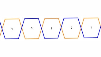
If you're wondering how Ethernet sends and receives information, check out my other blog here!