PCB Predicament? Not Anymore With 3D Printing!
2024-01-26 | By Will Siffer
Motivation to Make:
This week I decided to try to get some work done on that train project I started over a year ago. Sometimes, with a project with a lot of complicated parts, it's easy to get discouraged, and I am having trouble getting this one done now that I am working full-time and don't have all the extra time I had when I was at Purdue.
I found a great controller that would be perfect for controlling my train; the only issue is that it doesn't currently have an Arduino in it with programmable buttons and joysticks! What a bummer!
So here I am, ready to design a perfect PCB, but the controller has complicated mounting features that are tough to measure, so I tried my best to measure and really struggled. Then I had a great idea: What if I used my 3d printer to print test PCB shapes until I found one that fit?!
The Devil is in the details!
The overall process is relatively straightforward, but I figured I would write this blog post for someone to get inspired and maybe use a similar technique for their project.

Rough sketch of what I thought the PCB may look like
The picture above was my first attempt at making a template that could fit buttons and IO for everything I needed on the PCB. There are a bunch of resistors I need to add as well. One thing I noticed right away was that this was going to be a big challenge. I still need to put a bunch of resistors on this PCB, and it already is really full!
I originally planned on using only through-hole components, but after seeing this, there is a big chance that I need to work on my surface mount soldering in the interest of space.
Ignoring my issue with resistor placement, let's just 3D print the PCB anyway!
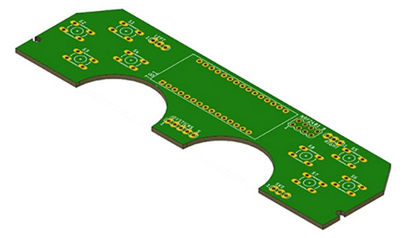
After exporting my PCB to my CAD software, I was able to see the physical size of my PCB for the first time in 3D. I liked the way it looked, and I was optimistic that it was going to work!

Initial 3D rendering of my control board PCB.
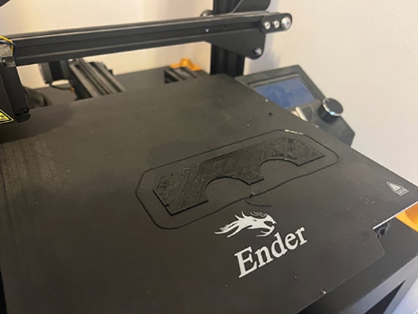
Since I liked the way it looked, I sent the PCB file to my 3D printer, where I adjusted the height to just a few layers so it would be a quick print. I didn't need the full thickness since all I was doing was checking fitment anyway.
My one recommendation if you are doing this yourself would be to try to make a quick 3D model of the piece you are trying to fit the PCB into as well. This is something I did not do, and it caused me some issues down the line (foreshadowing).
But ignoring my own advice, I pushed onward and printed the design on my 3D printer using Polymaker Polylite PLA from DigiKey.com. (I know! I forgot DigiKey sold 3D printing supplies too, but you can't beat the shipping speed!)

This may just be the worst 3D print I have ever done, but all I need is dimensional accuracy so I will take it. As you can see the printer tried to make the component holes, and it failed miserably. This is why we can't just 3D print a PCB and expect it to work great. As awesome as my 3D printer is, it is not the catch-all tool that some people claim it to be.
But with that said, this template will work for now.

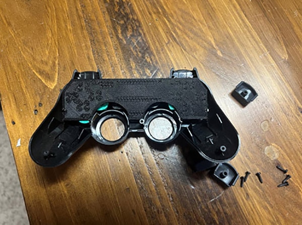
Well. Sometimes things don't go according to plan, do they? It does not quite fit into the pattern, but that's okay because the parts that need to fit do fit. The holes on the side are all in the right spot, and the cutouts for the joysticks are the correct radius. I may even be able to make the arcs smaller to make more room for myself. I am happy with this because it gave me the chance to learn and try again.
I hope this process expanded your view on what was possible with CAD and 3D printing. Until I tried this method myself, I was skeptical about how easily I would be able to use each of these CAD tools together to make my life easier. Whether you try this yourself or not, I hope this blog post inspired you to try something new and to think outside the box with your next project!

Have questions or comments? Continue the conversation on TechForum, DigiKey's online community and technical resource.
Visit TechForum


 中国
中国