制造商零件编号 SC1111
SBC 2.4GHZ 4 CORE 4GB RAM
Raspberry Pi
Single Board Computers Raspberry Pi SBC
In my previous two articles, I covered how to perform object detection on the Raspberry Pi and how to modify a model to detect custom objects. In this article, we’ll be bringing that technology to an XRP robot to find and pick up some custom-made baskets!
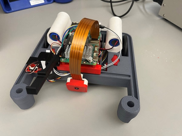
To connect the power of the Raspberry Pi to the XRP robotics platform, we’ll be using a UART connection between the Raspberry Pi and Pico W. The Raspberry Pi will provide data on the size and location of the object’s bounding box in the camera frame, while the Pico will use that data to control the motors and peripherals on the XRP. If you’d like to replicate this project, I highly recommend using a Raspberry Pi 5, as it performs inference much faster than the Pi 4 (about 3-4 times faster in my testing)! As usual, all the code can be found in this GitHub repo. All the code for the XRP is in a file named “XRPCode.py”.
There are many options to connect the Raspberry Pi to the Pico W. Wi-Fi and Bluetooth are reasonable options but suffer from higher latency than a UART connection, so we went with UART. When combining robotics with image detection, latency is one of the more critical considerations. Stale data can make it very hard to control your robot, which we’ll talk about later. We’ll be using the GPIO UART pins on the Raspberry Pi and the UART pins available on the 6-pin motor 4 connector on the XRP (pins 8 and 9).
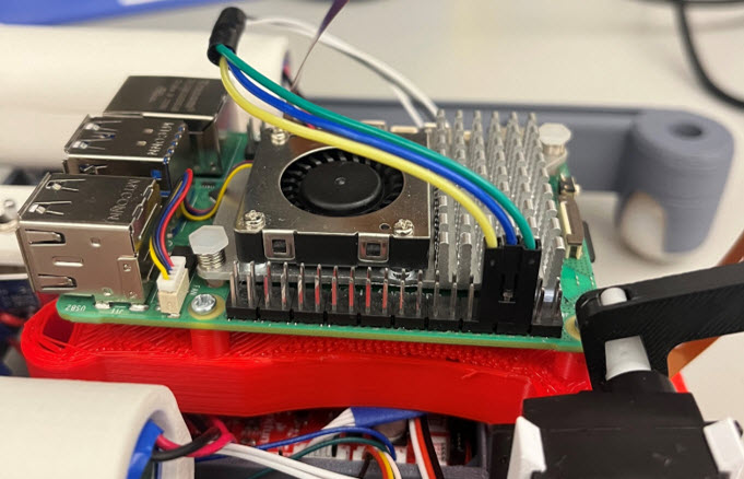
The code on the Raspberry Pi is a slight modification from my previous article on object detection. Instead of just writing the code to the terminal, it also writes the code over the UART pins on the Raspberry Pi’s GPIO header.
 The centroid of the object bounding box and its dimensions are all we need to control our robot.
Let’s break down the code on the XRP! Here are all the libraries to be imported. We’re using the Qwiic button library because we added a Qwiic button to our XRP, which is easier to access than the onboard user button. If you’d like to use the Qwiic button as well, you’ll need to follow this thread and upload the correct files from this GitHub repo to your XRP. You’ll also need to go into the I2C_micropython file and modify the I2C frequency to match the IMU on the XRP (400000Hz). If that sounds intimidating, don’t worry! You can always just modify the code to use the onboard button.

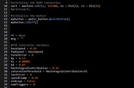
After importing the libraries, we’ll initialize our objects and variables. First, we initialize the UART connection. Pay special attention and make sure the baud rate in your constructor matches your Raspberry Pi. Then we initialize the Qwiic button. If you’re using the onboard user button instead, omit this constructor. Let’s not worry about the variables too much right now, as their purpose will become clear later.
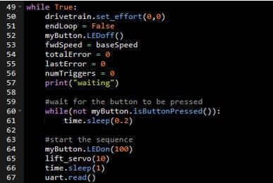
Let’s move to the super loop. We wanted this program to be able to run multiple times with the press of a button, which is useful when testing or demonstrating the robot! The first chunk of code from lines 50-57 resets all the variables from the last time we ran the robot. The small chunk of code on line 60 and 61 stops the code from moving further until the button is pressed. If you’d like to use the onboard button, you can simply use the wait_for_button() function included in the XRP library. Finally, the code on lines 64 to 67 turns the button’s LED on (remove this if not using the Qwiic I2C button), resets the servo to a good position for picking up the basket (you may have to adjust this), and flushes the UART buffer by reading all existing data in it.
Now we enter the main loop, where our robot will find the basket and pick it up. First, we check to see if we have a UART transmission from the Raspberry Pi. If we do, we wait for a really short time to let all the data come in and we read a single line of data. If the read occurs successfully, we decode the line and split it into an array! Remember, the incoming data from the Raspberry Pi is formatted like a CSV, so splitting based on commas will yield the following data array:
[detected?,xcentroid,ycentroid,width,height]
These values will give us all the necessary data to direct our robot toward the basket and stop it when it’s close enough. The area variable will be used to calculate the area of the bounding box later in the code.

Before we get to the meat and potatoes of our code, we’ll need to talk about what a PID controller is. A PID controller stands for proportional, integral, derivative controller and is used to control physical systems. Let’s say you’re learning to ride a bike with a friend. Your friend helping you to keep your balance is a good example of a PID controller. Your friend watching how far off balance you are is the proportional aspect. The farther off balance you are, the stronger they correct you. The integral term is akin to being slightly off balance for a while and your friend recommending a stronger correction. Finally, the derivative term is like your friend holding you to stop you from wobbling, it dampens sharp changes!
For our robot, the PID controller will help center the basket in the middle of the camera frame. If the basket is in the right side of the frame, the controller will drive the left wheel faster to recenter it. There’s a lot more to a PID controller, but this high-level description should help you edit the Kp (proportional), Kd(derivative, and Ki(integral) variables initialized earlier to adjust the strength of each component. As a general guideline, adjust Kp if the robot doesn’t correct fast enough, Kd if it’s responding too harshly to changes, and Ki if it can’t respond to small deviations. You’ll have to retune your controller for your use case, as everything from the battery level to the surface can impact performance!
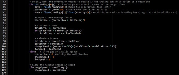
Let’s now get to the code. I won’t dive too far into the details of how this works (PID controllers are deserving of their own separate write-up), but it’s well-documented here, so feel free to read through it yourself. We’d like to essentially see how far away our basket is from the center of the camera frame and adjust how much power we deliver to each wheel based on that. In this section of code, we use a PID controller to decide exactly what the difference in power between the two wheels should be.
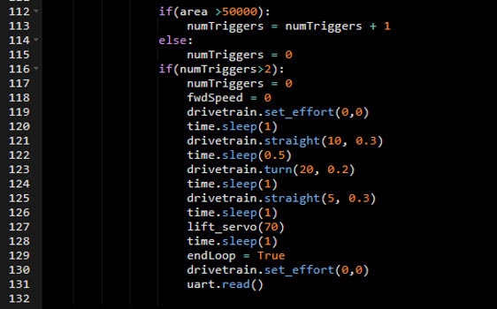
The next code snippet shows how we’ll be detecting if the object is close enough to pick up. Remember the area value we calculated earlier? We’ll be using that here to check if it’s exceeded a certain threshold. If it has, we’ll add a point to our counter numTriggers. If the area is larger than this value for two consecutive readings, we initiate our pickup sequence. We check for two consecutive reports of an area larger than 50000 to prevent noisy data from accidentally triggering the pickup sequence. Depending on your application, you may find you have to tweak the threshold for both numTriggers (adjusts the sensitivity of the trigger), and the area threshold (adjusts distance from your object). In my testing, I’ve found this method of checking the area of the bounding box to be accurate within 1-2cm!
We also set a Boolean flag (endLoop) to be true, to inform our program that it’s time to reset the robot in preparation for another run.
If we aren’t close enough to the basket to pick it up, we use the changeSpeed variable we calculated earlier to assign effort values to each motor. By adding to one and subtracting from the other, we can ensure that we’re always turning towards the basket!

And voila! You now have an XRP robot empowered with object detection!
In our testing, we’ve found this setup to be fairly reliable, especially with a high contrast background. Because our object detection program is trained on a relatively small number of images, all taken in the same location, with the same lighting conditions, it can struggle when it encounters similar objects. You should also take note that the performance of the robot is greatly limited by the speed at which the Raspberry Pi can perform inference (around 80ms for a Pi 5 and 300 for a Pi 4). By using a more powerful board, you can make an even more accurate robot!