制造商零件编号 DKS-LEARN2SOLDER-THT
THRU-HOLE SOLDER KIT W/555
DigiKey Kit (VA)

The DigiKey LEARN2SOLDER Kits are meticulously designed for individuals who are taking their first steps into the world of soldering, making them an excellent choice for beginners eager to grasp the fundamentals of this essential skill. These kits also serve those who possess a foundational knowledge of soldering but wish to enhance their techniques and proficiency. Available in two distinct versions, the kits cater to a variety of learning needs. The through-hole variant is an outstanding option for novices looking to master basic soldering techniques. It includes components with leads that penetrate the circuit board, providing a hands-on opportunity to learn and practice essential skills. On the other hand, the surface mount variant offers a more advanced soldering experience. This version introduces participants to the intricacies of soldering components that are mounted flat against the circuit board, allowing for a deeper understanding of advanced practices and techniques. With these comprehensive kits, users can cultivate their soldering abilities and build confidence in their craftsmanship.
Note that the circuit used in these kits is not a standard 555 timer circuit (as the load can change the frequency), so it should not be used for typical applications unless the goal is simply to blink some LEDs. However, it does feature the lowest component count.
 The schematic
In this setup, Resistor R5 and Capacitor C1 are utilized to control the timing mechanism. By connecting these components to the output from pin 3, they effectively set the timing parameters. While this configuration may not be the most optimal solution, it is functional and achieves the desired outcome.
Please note that D3, R3, D4, and R4 are included exclusively in the surface mount kit, and their use is completely optional, depending on your eyesight and dexterity.
‘Soldering’ in electronics uses heat to melt solder. Solder is a soft metal alloy. We use this to make a strong electrical connection.

Leaded solder leaves a shiny finish when applied correctly. Lead-free solder usually looks dull. Leaded solder requires less heat to melt than Lead-free and why many deem Leaded solder to be a better choice for hand soldering.

Lead is toxic and should never be consumed; it poses serious health risks if ingested. However, using lead-based solder can make hand soldering more manageable and effective for electronics and metalwork. To ensure your safety while soldering, follow these important guidelines:
The metal surfaces you want to join will need to be free from oxidization. Soldering uses a chemical called flux (also called Rosin) to address this. When heated, the flux breaks down the metal oxides allowing the solder to flow freely to connect what you are joining.
Most solder wire features a hollow core that is filled with flux. As the wire is heated during the soldering process, the flux is released, facilitating a strong bond between the metals being joined. Flux can also come in a paste or liquid to be applied separately.

Flux fumes do not contain lead, however, it is still important to minimize your exposure to these fumes, as breathing them in excessively can lead to respiratory irritation and other health issues. To ensure a safer working environment while soldering, always try to work in a well-ventilated area. For even greater protection, consider using a fume extractor, which is specifically designed to capture and filter the harmful fumes produced during the soldering process.
While the chance of injury is low, small pieces of molten solder or sharp metal shards can unexpectedly dislodge and fly into the air when cutting leads from electronic components. These tiny projectiles pose a significant risk to your eyes, which are invaluable and irreplaceable. To protect yourself from potential injury, it is crucial to wear appropriate eye protection, such as safety goggles or glasses specifically designed to shield your eyes from debris and impact.
When setting up your workspace, it’s important to choose a surface that can tolerate potential damage from high temperatures. To safeguard your table, consider using a silicone mat, which is designed to withstand extreme heat and protect against spills. Alternatively, you can lay down old newspapers or cardboard to create a protective barrier. Just ensure that whatever you use can handle the risk of molten metal being accidentally dropped, as temperatures can exceed 700°F (370°C). This will help prevent damage to your furniture and keep your work area safe.
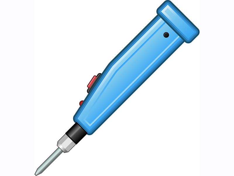
Be cautious when using the soldering iron! The saying, “If it smells like chicken, you’re holding it wrong,” is a reminder to handle it safely. Always place the iron back in its stand when you're not using it. For leaded solder, heat your iron to around 700°F (370°C), and for lead-free solder, set it to about 750°F (400°C). If you have a non-adjustable soldering iron, don't worry; it will reach the necessary temperature. This type typically doesn’t have a temperature display, so it’s normal to wait a few minutes for it to warm up.
Soldering requires the use of both hands. It's highly recommended to use a PCB vice, PCB holder, or third-hand tool for better stability. However, in the following tutorial, both the through-hole and surface mount kits were assembled on a mat to demonstrate that a holder is not strictly necessary. If you do have one, it's best to use it!

Effective through-hole soldering requires a careful balance of the following:
To ensure a proper solder joint, be mindful of the following tips:
By following these guidelines, you can achieve reliable and effective solder joints.
Things you will need:
Turn on your iron, it will take a bit to warm up. Do you have eye protection on?
Before we put down our first solder joint, clean the tip to remove oxidization by pulling it on a ‘brass sponge’ or a sponge that is slightly damp with water.
Make it a habit to clean the tip every time you remove the iron from its holder.

Now put a bit of fresh solder on the tip. This is called ‘tinning the tip’. Tin the tip whenever you will not be using your iron for a bit OR before you turn off your iron. This helps protect the tip from oxidization.
.gif?la=en&ts=a87be474-596d-47d7-84bb-eb1232185fb7 "DKS-LEARN2SOLDER-ND: Tips on Soldering, The Schematic, and more...")
Also referred to as the Bill of Materials (BOM):
| Item | Reference Designator | Description | DigiKey Part Number |
|---|---|---|---|
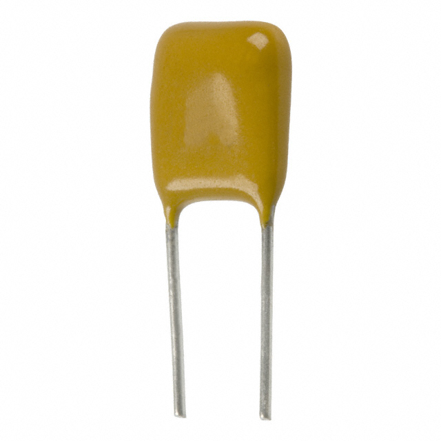
| 1 | C1 | Capacitor, Ceramic, 0.1uF, Radial | 399-14036-1-ND |
| 2 | D1 | Red LED (Light Emitting Diode), 3mm, Radial | 160-1943-ND |
| 3 | D2 | Green LED (Light Emitting Diode), 3mm, Radial | 160-1942-ND |
| 4 | R1 | Resistor, 1k Ohm, 5%, 1/4W, Axial | 738-CF14JA1K00CT-ND |
| 5 | R2 | Resistor, 120 Ohm, 5%, 1/4W, Axial | CF14JT120RCT-ND |
| 6 | R5 | Resistor, 3.3M Ohm, 5%, 1/4W, Axial | CF14JT3M30CT-ND |
| 7 | U1 | IC, 555 Timer, 8-DIP | 296-1857-5-ND |
| 8 | J1 | IC Socket, 8-DIP | 2057-ICS-308-T-ND |
| 9 | BT1 | Coin Cell Battery, 3V, 20mm Dia, 3.2mm thick | 1908-1385-ND |
| 10 | PCB | The Learn2Solder PCB |
The socket features a distinctive notch located at one end. When positioning the socket, ensure that this notch is oriented toward the lower edge of the printed circuit board (PCB). This particular alignment serves as a clear marker for identifying the location of pin one, which is crucial for proper pin configuration and connection.

![]()
To securely hold the socket in place, carefully bend one lead at each of the opposite corners outward. This will help stabilize the socket and prevent it from shifting during use. Make sure to adjust the leads gently to avoid damaging them.


After ensuring your soldering iron is heated to the appropriate temperature, carefully place the tip against both the pad and the pin you wish to solder. Gently introduce the solder wire into the joint while keeping the iron in place. As the solder begins to melt, it will flow into the connection between the pad and pin. Ideally, at this point, the pad should take on a shiny silver appearance, with the solder forming a snug, secure bond around the pin. The final result should resemble a chocolate chip, where the solder is embracing the pin, indicating a successful solder joint.


When working with LEDs, it's important to note that they have polarity, meaning they will only function if connected in the correct orientation. In this case, we are dealing with 3mm diameter 'radial' LEDs, which are characterized by both of their leads extending from the same end. Among these leads, the longer one is designated as the positive lead, officially referred to as the Anode. This is crucial information for ensuring proper installation; if the leads are reversed, the LED will not light up and may even be damaged. Always double-check the orientation before making connections to ensure optimal performance.


D1 appears clear when it is not illuminated. To begin the installation, carefully insert the positive lead of the LED into the designated top hole of the circuit board. Once the lead is in place, align the negative lead with the other hold and gently drop the LED down so that it sits securely in the hole. To ensure that the LED remains stable during the soldering process, spread the leads apart slightly; this will hold the LED firmly in position.


LED 2 (D2) is green when it is off. Please install this LED in the same manner as D1.
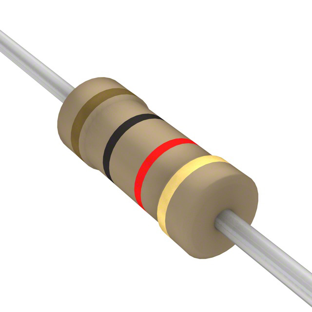
Find the R1 resistor, which is a 1kΩ (1,000 Ohm) component. Its color code is Brown, Black, Red, and Gold. If you need assistance with the resistor color code, feel free to use our Resistor Color Code Calculator. This is an axial resistor, meaning the leads extend from both sides, similar to an axle.
Bend it into a ‘U’ shape, like this…

Carefully insert the leads and spread them at a 45-degree angle to ensure they stay securely in place and do not fall out. Avoid a steeper angle, as this can complicate the cutting process later on.


Repeat the same process with the capacitor, C1…


and the last two resistors:
R5 = 3.3MΩ resistor = Orange, Orange, Green, Gold
R2 = 120Ω resistor = Brown, Red, Brown, Gold
Carefully solder each component into position, ensuring that all connections are secure and free of any excess solder. Make sure to double-check the alignment of the components before soldering to avoid any misplacement.


To cut the leads, carefully position your finger over the lead wire that you want to trim. This will help prevent the lead from shooting away unexpectedly when you make the cut. Ensure you have a steady grip and use sharp cutting tools for a clean cut.


After you finish soldering, make sure to tin the tip of your soldering iron and then turn it off.
Gently place the integrated circuit (IC) on a flat, level surface. Carefully roll the IC to slightly bend its pins until they are aligned perpendicular to the body of the chip. Apply even pressure throughout the process to avoid damaging the IC or its connections. Repeat this process for the pins on the opposite side as well. If done correctly, both rows of pins should be parallel.

Identify the marker for Pin 1 on both the IC (indicated by a circle) and the PCB, and carefully insert the IC into the socket, ensuring they align correctly.

Ensure that all pins are properly aligned and seated in the socket before pressing the IC down firmly.
To install the battery, hold it with the ‘+’ side up. Press down the center tab on the PCB and then slide the battery in.


If everything went as planned, you should see your LEDs blinking, indicating that your circuit is functioning correctly. This setup is designed to run for several days on a CR2032 battery, providing a reliable power source for your project. If you choose to use a CR2016 battery instead, you may notice that the duration of operation is shorter, but both options are compatible. Remember to double-check your connections to ensure everything is in order and enjoy the satisfaction of seeing your hard work pay off!
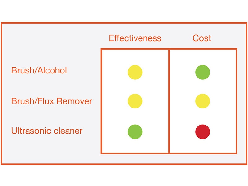
You may choose to stop here, but if you want your circuit to continue functioning effectively over the years, it’s highly recommended that you thoroughly clean off any residual flux. Flux can corrode the copper traces over time if it is left untouched, which can lead to circuit failures or performance issues down the line. Taking the extra time to eliminate this remaining flux will help ensure the longevity and reliability of your circuit.
To clean the PCB, start by dampening a piece of paper towel with isopropyl alcohol, or use a dedicated flux removal product if you have one. Place the wet paper towel over the area you intend to clean. Next, take an old toothbrush or a similar brush and gently scrub the wet paper towel with the bristles. This will help lift the flux from the solder joints. Repeat this process for each solder joint you've made.


Don’t forget to wash your hands. Solder is good for PCBs, not for people.
Also referred to as the Bill of Materials (BOM):
| Item | Reference Designator | Quantity | Description | DigiKey Part Number |
|---|---|---|---|---|
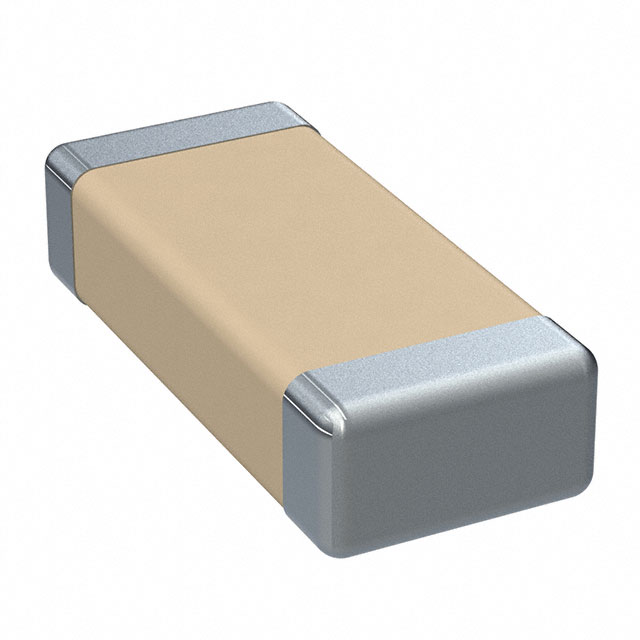
| 1 | C1 | 1 | CAP CER 0.1UF 50V X7R 1206 | 399-C1206C104K5RAC7210CT-ND |
| 2 | D1 | 1 | LED ORANGE-RED CLEAR 1206 SMD | BL-HJE33A-AV-TRBCT-ND |
| 3 | D2 | 1 | LED WHITE 0805 SMD | 1080-EAST2012WA1CT-ND |
| 4 | D3 | 2 | LED ORANGE CLEAR 0603 SMD | 1497-1428-1-ND |
| 5 | D4 | 3 | LED GREEN CLEAR 0402 SMD | 1516-QBLP595-IG5CT-ND |
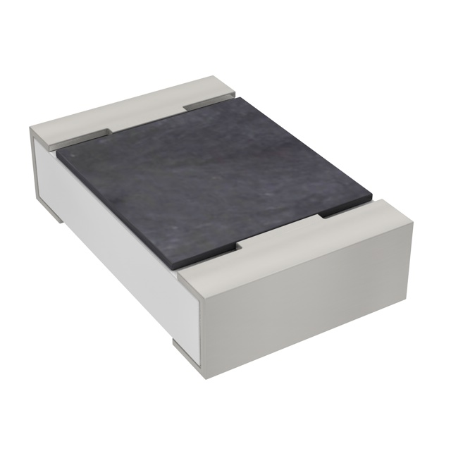
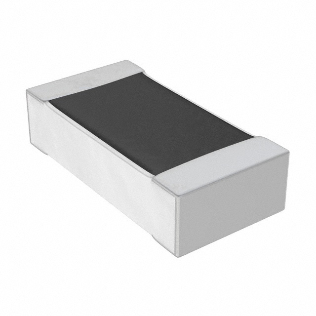
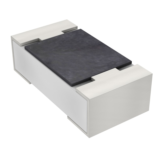
| 6 | R1 | 1 | RES 510 OHM 5% 1/4W 1206 | RMCF1206JT510RCT-ND |
| 7 | R2 | 1 | RES 43 OHM 1% 1/8W 0805 | 311-43.0CRCT-ND |
| 8 | R3 | 2 | RES 590 OHM 1% 1/10W 0603 | 738-RMCF0603FT590RCT-ND |
| 9 | R4 | 3 | RES 1.69K OHM 1% 1/16W 0402 | YAG3044CT-ND |
| 10 | R5 | 1 | RES 3.3M OHM 1% 1/4W 1206 | RMCF1206FT3M30CT-ND |
| 11 | U2 | 1 | IC OSC SGL TIMER 2.1MHZ 8-SOIC | 296-1336-1-ND |
| 12 | BT1 | 1 | BATTERY LITHIUM 3V COIN 20MM | 1908-1385-ND |
| 13 | PCB | 1 | THRU-HOLE/SMD SOLDER PCB W/555 |
D3, R3, D4, and R4 are optional, depending on your eyesight and dexterity. The project will function correctly without these components but using them will give you bragging rights if you do. The mentioned parts are quite small, so we've included extra components for the 0603 and 0402 sizes, in case you accidentally damage one or send it flying off the table to join the dust on the floor.
Locate the footprint for the R5 resistor (3.3M). Heat a bit of solder onto one of the two pads. It should form a smooth surface, so use a sweeping motion to one side instead of lifting the iron straight up. If there is too much solder, clean the tip of the soldering iron with a sponge and gently draw it across the pad to create a round shape.


Carefully grip the resistor with tweezers and position it directly above the designated pads on the circuit board. Next, take your soldering iron and place the tip against the solder pad. Allow the heat to transfer to the solder, causing it to melt and reflow. Place the resistor onto the pads and ensure that it aligns properly with the pads as the solder liquefies, creating a secure connection once it cools.


Once the component is securely anchored in place, proceed to apply solder to the second pad. As you do this, make sure to inspect the first pad to ensure that it has an adequate amount of solder and that it appears to have 'wet-out' properly; this means the solder should have spread evenly over the surface, creating a solid connection.
If you encounter any issues with the solder not flowing smoothly, consider applying additional flux. Flux helps to clean the surfaces and improve the flow of the solder, making it easier to achieve a reliable and effective joint.


Please repeat the same procedure for C1, R1, and R2.
If you are using the SMT kit, you probably know that LEDs have polarity and can only operate in one direction. Start by placing D1 down and touch the leads of the digital multimeter (DMM) to it, ensuring that the DMM is set to check continuity or perform a diode test. If the LED does not light up, reverse the leads, or turn the LED around. When the LED lights up, the lead that has the red lead attached is the positive one. Position D1 with the positive end facing towards the top edge of the PCB (we’ve marked a ‘+’ sign next to each LED footprint). Finally, solder the LED in place.


To ensure accuracy, you can easily verify that you soldered the component in the correct direction by positioning the DMM (Digital Multimeter) leads as shown.


Repeat the same procedure with D2, ensuring that you check the polarity before soldering it in the same manner.
To begin the installation of the integrated circuit (IC), start by applying a small amount of solder to one of the corner pads of the IC. This initial step is crucial, as it helps secure the IC in place and ensures a solid connection. It's important to heat the pad for just a moment and then apply the solder, allowing it to flow smoothly onto the pad without forming a large blob. This will create a stable base for further soldering the remaining pins of the IC.


Position the IC on the footprint, ensuring pin one is properly aligned (indicated by a small circle).


Hold the IC with your tweezers and heat the solder on that pad so the IC sits flat on the footprint.


If you encounter a solder bridge while working with your circuit, first make sure to clean the tip of your soldering iron. Next, carefully drag the tip of the iron across the pins affected by the solder bridge. This should help melt the excess solder, allowing it to flow back into place or be absorbed by the iron. After you've finished, inspect the area to confirm that the bridge has been properly cleared.


To install the battery, hold it with the ‘+’ side up. Press down the center tab on the PCB and then slide the battery in.


If everything went as planned, you should see your LEDs blinking, indicating that your circuit is functioning correctly. This setup is designed to run for several days on a CR2032 battery, providing a reliable power source for your project. If you choose to use a CR2016 battery instead, you may notice that the duration of operation is shorter, but both options are compatible. Remember to double-check your connections to ensure everything is in order and enjoy the satisfaction of seeing your hard work pay off!
You may choose to stop here, but if you want your circuit to continue functioning effectively over the years, it’s highly recommended that you thoroughly clean off any residual flux. Flux can corrode the copper traces over time if it is left untouched, which can lead to circuit failures or performance issues down the line. Taking the extra time to eliminate this remaining flux will help ensure the longevity and reliability of your circuit.
To clean the PCB, start by dampening a piece of paper towel with isopropyl alcohol, or use a dedicated flux removal product if you have one. Place the wet paper towel over the area you intend to clean. Next, take an old toothbrush or a similar brush and gently scrub the wet paper towel with the bristles. This will help lift the flux from the solder joints. Repeat this process for each solder joint you've made.
Don’t forget to wash your hands. Solder is good for PCBs, not for people.