制造商零件编号 A000066
ARDUINO UNO R3 ATMEGA328P BOARD
Arduino
A task scheduler is a program that schedules, manages, and executes jobs or tasks in an operating system or application, even those requiring specific operation times. A washing machine or dishwasher would be one example of a task scheduler executing cycle times for cleaning clothes and dishes based on specific time intervals. These intervals are programmed in a microcontroller, which then executes various washing modes managed by the task scheduler. This article will explain how you can code and use a task scheduler to blink 3 LEDs simultaneously at various intervals.
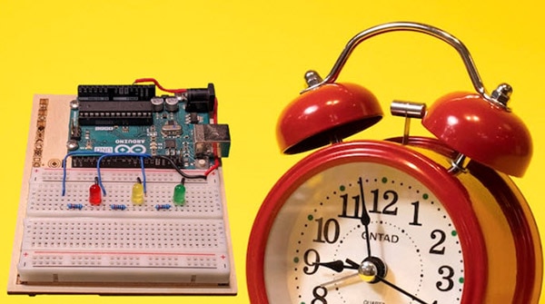
The task scheduler concept demonstrates how to automate and execute tasks at predetermined times under specific conditions. Sensors and digital switches can both set off conditions in a manufacturing setting. If the condition is true or false, the task will then run for a specific amount of time or duration. Once complete, the scheduler initiates the new task according to its conditional requirements. This demo concept illustrates blinking three LEDs at discrete or unique timing intervals and is constructed using three basic elements: a scheduler, the task, and the time interval.
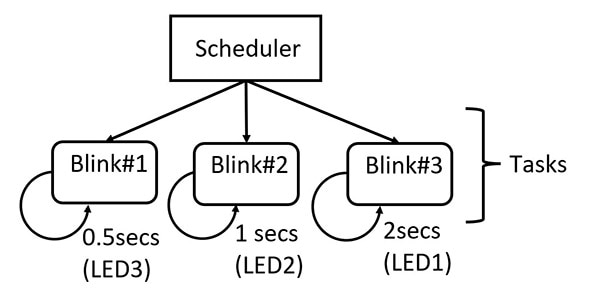 The Multi-Blink LED tasks scheduler.
Based on a conditional statement, the scheduler will initiate the Blink 1 task. The system’s current time will then be utilized to check the LED 3’s last toggle state. If the difference between the current time and the last toggle state time is greater than or equal to the defined blink interval time, then LED3 will blink. LED2 and LED1’s blink tasks will execute this same checking process used by LED3. The blink intervals used in the task scheduler demo are listed below.
This scheduling time interval process will continue until the task scheduler has been instructed to stop. There are a few unique aspects on display here — for one, a reset button can temporarily stop the task scheduler from completing the multi-blink tasks. Additionally, no delay() instructions are used in the code. Although the delay () instruction method provides a specific pause function of an executable instruction, the timing operation is inaccurate. For real-time systems, it’s imperative for the timing to be as accurate as possible. Therefore, a real-time operating system (RTOS) will use the system’s internal clock or timing feature to provide accurate time for activating events. The Arduino instruction millis() will provide accurate timing for the Multi-Blink Tasks Scheduler. You may find additional information on RTOS here.
Building an Arduino Task Scheduler is quite easy to achieve. You may use a library such as the Scheduler library to explore the concept of task schedulers. The Scheduler library can be easily installed, and once active, the example code will provide information for wiring three LEDs to the specific digital pins of an Arduino SAMD-based microcontroller board, such as the Due, Zero, or many of the MKR boards among others.
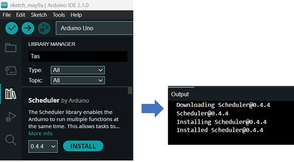 The Scheduler Library installed.
Running the Scheduler code on an Arduino Uno will cause a compilation error due to the ATMEGA328 microcontroller being incompatible with the Scheduler Library’s header file. An alternative solution is to use a faux Arduino Task Scheduler code:
// Define LED pins
const int LED_PIN_1 = 11;
const int LED_PIN_2 = 12;
const int LED_PIN_3 = 13;
// Define delay times
const long BLINK_TIME_1 = 1000; // 1 second
const long BLINK_TIME_2 = 500; // 0.5 seconds
const long BLINK_TIME_3 = 250; // 0.25 seconds
// Define task times
unsigned long task1Time = 0;
unsigned long task2Time = 0;
unsigned long task3Time = 0;
// Define task intervals
const long TASK_INTERVAL_1 = 2000; // 2 seconds
const long TASK_INTERVAL_2 = 1000; // 1 second
const long TASK_INTERVAL_3 = 500; // 0.5 seconds
void setup() {
// Set LED pins as output
pinMode(LED_PIN_1, OUTPUT);
pinMode(LED_PIN_2, OUTPUT);
pinMode(LED_PIN_3, OUTPUT);
}
void loop() {
// Check if it's time to run task 1
if (millis() - task1Time >= TASK_INTERVAL_1) {
task1Time = millis();
digitalWrite(LED_PIN_1, !digitalRead(LED_PIN_1)); // Toggle LED 1
}
// Check if it's time to run task 2
if (millis() - task2Time >= TASK_INTERVAL_2) {
task2Time = millis();
digitalWrite(LED_PIN_2, !digitalRead(LED_PIN_2)); // Toggle LED 2
}
// Check if it's time to run task 3
if (millis() - task3Time >= TASK_INTERVAL_3) {
task3Time = millis();
digitalWrite(LED_PIN_3, !digitalRead(LED_PIN_3)); // Toggle LED 3
}
// Add a delay to prevent the loop from running too fast
delay(10);
}
Open the Arduino IDE and copy and paste this code into the editor. The hardware components, Bill of Materials (BOM), and the electronic circuit schematic diagram required to build the Multi-Blink LED Task Scheduler are located here. You can use the hardware demonstrator electrical wiring diagram as an additional source of construction information for the task scheduler.
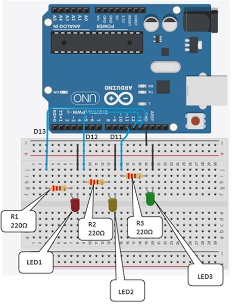 The Multi-Blink LED Task Scheduler solderless breadboard electrical wiring diagram.
The Multi Blink LED Tasks scheduler final assembly serves as another build reference for device construction.
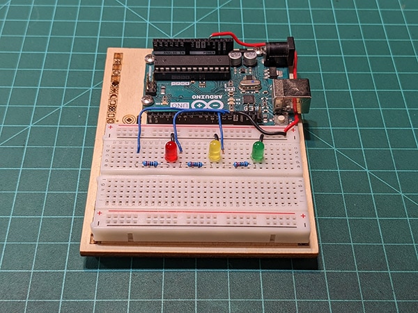 The Multi-Blink LED Task Scheduler.
The Arduino IDE’s pasted code can be compiled and uploaded to the Arduino Uno. LED 1 will blink at 0.5 seconds, with LED2 operating at 1 second and LED3 running at 2 seconds. The onboard LED will blink at 0.5 seconds due to being hardwired to the Arduino board’s digital pin 13. Explore the tasks scheduler further by changing the blink interval times and observing the LED’s responses. Aside from using discrete LEDs, you can modify the task scheduler device’s code to switch devices like servo motors ON/OFF at specific intervals. Click here to see the task scheduler in operation.