


制造商零件编号 FIT0096
BREADBRD TERM STRIP 3.20X2.00"
DFRobot
Many microcontroller projects require some form of user-input, like a button press, and produce some output to inform the user of the device’s current state or errors. Inputs are often simple components such as push-buttons, switches, and dials. Users can utilize LEDs as simple output devices. This how-to article covers the basics of connecting these simple physical components on an Arduino.
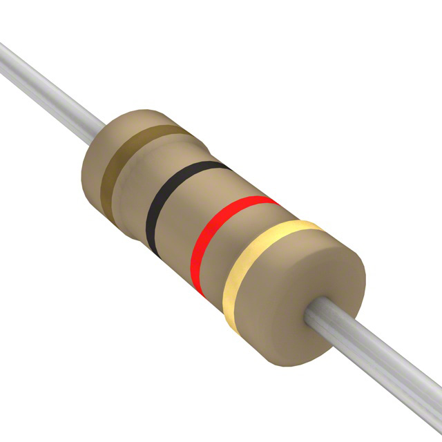
Blinking or color changing lights are among the most common devices used for communicating information to a user. Light emitting diodes, or LEDs, are easy to connect and operate in a microcontroller project. The most common method connects the anode of an LED to a digital pin and the cathode to ground through a current limiting resistor, which is needed for controlling the amount of current through the LED to prevent it from getting damaged.

The LED is connected to a digital output of the Arduino. This pin might either be in a HIGH state, where it outputs 5 V, or it might be LOW, where it has the same potential as GND. By changing the state of the digital pin, the LED can be turned on and off.
External slide switches provide a simple method for users to interact with an electronic device. The simplest form is the SPST switch, which stands for Single-Pole, Single-Throw. The number of poles on a switch describes how many separate circuits the switch can control, and the throw refers to the individual positions that the poles can connect to. The SPST switch, therefore, either closes a circuit or leaves it open:

Note that the simple SPST switch performs the same way regardless of whether the circuit uses a pull-down or pull-up resistor.
The example below uses an SPDT (single-pole, double-throw) slide switch with three contacts. The slider moves between two positions and connects the common center pin to either the left or the right pin, which are connected to GND and +5 V, respectively:

The center pin of the switch then connects to a digital pin on the Arduino to allow the software to determine the state of the switch:


It’s possible to build relatively complex circuits by combining the components discussed above. In the example below, a user wants to control a green LED with a slider-switch. It simulates a machine -- something like a concrete mixer.
The green LED turns on while it’s running. Furthermore, the circuit has to contain a push button that activates a locking mechanism that will prevent the blender from getting activated while the lock is engaged. A flashing red light is required to let the operator know when the lock is activated.

This is the accompanying Arduino sketch:
/bool lock = false;

unsigned long c = 0;

// The components are connected to these pins on the Arduino
const unsigned short int GREEN_LED = 9;
const unsigned short int RED_LED = 8;
const unsigned short int SW = 4;
const unsigned short int BTN = 2;

// This interrupt function is called whenever a falling edge is detected
// on the input that's connected to the push-button
void changeLock(void)
{
  // If the interrupt happens, change the state of the lock by inverting
  // the current state (if lock is true, it will become false and vice-versa)
  lock = !lock;
}

void setup()
{
  Serial.begin(9600);

  // Configures the specified pin to behave either as an input or an output.
  pinMode(GREEN_LED, OUTPUT);
  pinMode(RED_LED, OUTPUT);
  pinMode(SW, INPUT);
  pinMode(BTN, INPUT);

  attachInterrupt(digitalPinToInterrupt(BTN), changeLock, FALLING);

  // Turn both LEDs off
  digitalWrite(GREEN_LED, LOW);
  digitalWrite(RED_LED, LOW);
}

void loop()
{
  // If the lock is engaged, disable the green LED
  // and flash the red one instead.
  if(lock)
  {
    // Disable the green LED
    digitalWrite(GREEN_LED, LOW);

    // This simple check controls the flashing speed of the red LED.
    // millis() returns the number of elapsed milliseconds since the
    // program has started. The if checks whether 500 milliseconds have
    // passed before it toggles the state of the LED.
    if ((unsigned long)(millis() - c) >= 500)
    {
      // Toggle the LED
      digitalWrite(RED_LED, !digitalRead(RED_LED));
      // Store the last time that the LED's state was changed
      c = millis();
    }
  }
  // If the lock is disabled, turn the green LED on if the
  // slider-switch is in the 'on' position and turn the
  // red LED off.
  else
  {
    digitalWrite(RED_LED, LOW);
    digitalWrite(GREEN_LED, digitalRead(SW));
  }
}
An interrupt is attached to the pin of the Arduino that is connected to the push-button component. It fires when the button gets pressed and calls the changeLock() function. In the main loop of the sketch, the red LED flashes if the lock was engaged. Otherwise, the green LED is enabled if the switch is in the ON position:

Many devices have knobs that the user can turn to make an input. This article, so far, has only discussed digital input devices that could either be “on” or “off”. However, a potentiometer gives users an analog input option that the Arduino can process in a sketch:

A potentiometer provides a variable resistance. In this example, the potentiometer has three pins. The center pin is connected to the wiper that moves between the left and right pin (which are attached to GND and +5 V, respectively). Internally, these two end pins are connected with a resistive material that the wiper also touches.
Note that in this setup, the value of the potentiometer doesn’t matter because it drops some of the input voltage depending on the current resistance, which is determined by the distance of the wiper to the two end contacts.
When the wiper moves farther away from the GND reference, the output comes closer to the supply voltage. If the wiper moves the other way, the output comes closer to GND.
Use the analogRead() function to read the potentiometer value in the Arduino program:
int value = analogRead(A3);
This will give you a value between zero (turned all the way to the left) and 1023 (fully on).
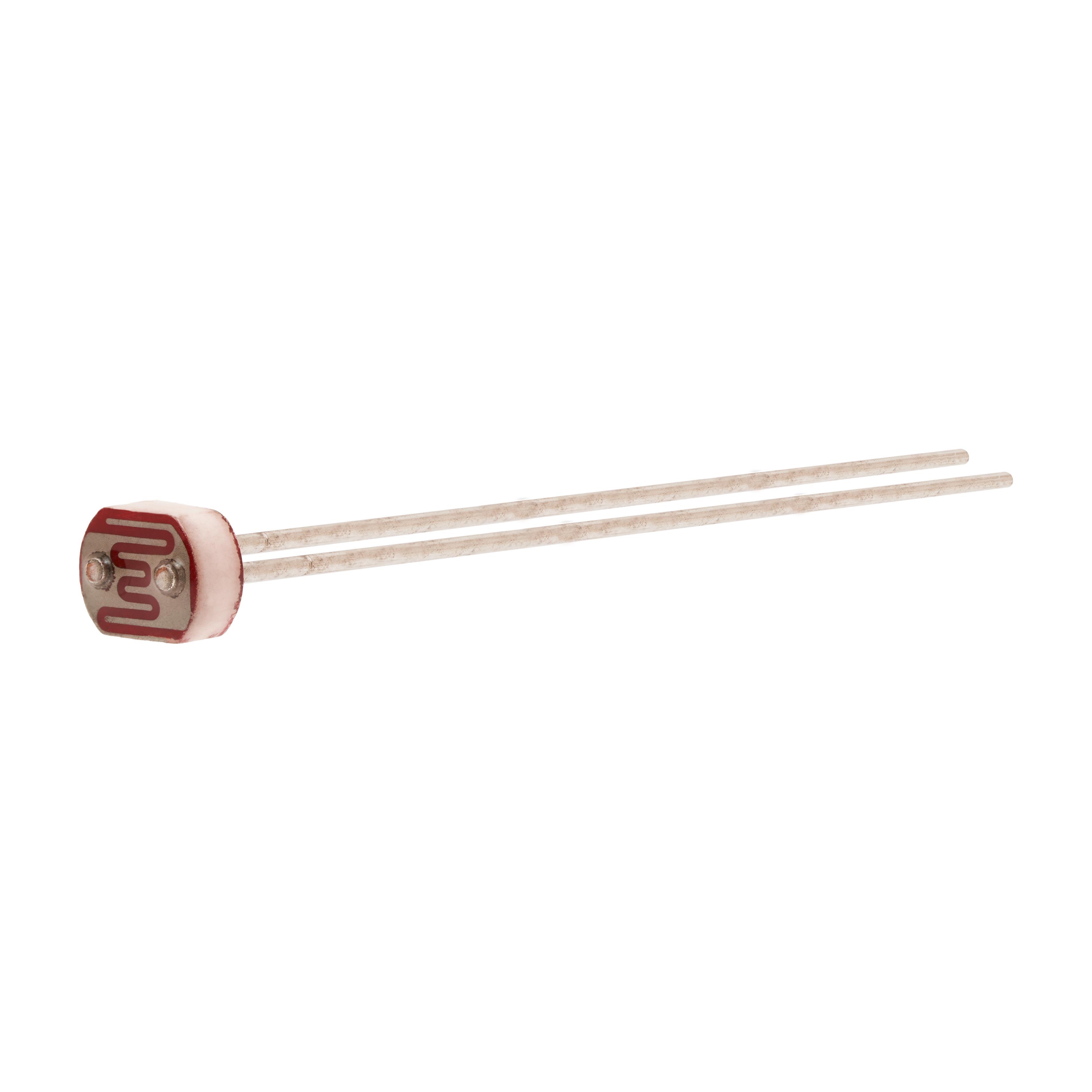
A photoresistor is somewhat similar to a potentiometer in the way that it changes its resistance when the environment changes. When a voltage divider (which uses such a device as the second resistor) is connected to an analog input of an Arduino, it’s possible to detect when the voltage on that pin adjusts due to the change in resistance. A minimal setup for a photoresistor looks like this:

As mentioned, a second resistor is required to form a voltage divider. Without it, the Arduino’s analog input pin would connect directly to GND and would only be able to measure the ground potential.
Users can read the voltage level of the input pin with the analogRead() function, as described above. The resulting value relates to the resistance of the photoresistor. As the light intensity increases, the resistance decreases and the value that the analogRead() function delivers gets closer to 1023.
Photoresistors can be used in a wide variety of applications, for example, in an automated light switch with a slider:

Note that the example above uses a transistor to drive the light bulb because it draws more current than the Arduino’s digital output pin can safely supply. Instead, the Arduino controls the transistor which acts as a switch.
Here’s the code that goes along with it:
#define POT A3
#define THRESHOLD 700

void setup()
{
  Serial.begin(9600);

  pinMode(13, OUTPUT);
  pinMode(POT, INPUT);

  digitalWrite(13, LOW);
}

void loop()
{
  if(analogRead(POT) < THRESHOLD)
    digitalWrite(13, HIGH);
  else
    digitalWrite(13, LOW);

  delay(100);
}
When using a switch that breaks the circuit in conjunction with digital electronics, the input pin might be open and left floating. In such a case, the state of the pin is not defined. It might be HIGH or LOW. However, one can overcome this issue by adding pull-up or pull-down resistors:

The use of pull-down or pull-up resistors prevents such an indeterministic state on the input pins. Pull-down resistors pull the pin LOW when the switch is open, and pull-up resistors ensure that the input pin will read a HIGH state in such a case.
LEDs can serve as a simple output method for communicating information to a user. The Arduino can control an LED by pulling one of its digital pins HIGH or LOW. An LED should always be accompanied by a current limiting resistor to prevent it from getting damaged.
Buttons and switches represent the simplest form of user input. Those are, however, only digital. A user can either press a button or not. Potentiometers and photoresistors, however, can be used for analog inputs. Both are varying resistors, and they can be used to drop the voltage that is present on an analog input pin. This change in voltage can then be detected and the application can react to it.

Have questions or comments? Continue the conversation on TechForum, DigiKey's online community and technical resource.
Visit TechForum


,TO-226_straightlead.jpg)


 中国
中国