Driving Low-Current LEDs
2016-02-12 | By Dave Knight
LEDs / Discrete / Modules Resistors
LEDs are used everywhere for status indicators, light sources, and more. This blog covers the basics of biasing low-current LEDs.
LEDs are biased with a current, not a voltage, as evidenced by the fact that LED datasheets tend to have plots of luminous intensity versus forward current. Also, forward-voltage drops are not tightly controlled and vary with current. See figure 1, from the datasheet for the LTST-C171GKT green LED.
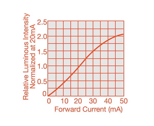
Figure 1: Relative luminous intensity for an LED
Image Source: LTST-C171GKT
A current-limiting resistor is a common way to control the amount of current flowing in a low-power LED. The resistor prevents the LED from clamping the power rail to the LED’s forward voltage, and drawing excessive current (see figure 2). The resistor value should be chosen to keep the forward current less than the datasheet’s maximum forward-current rating.
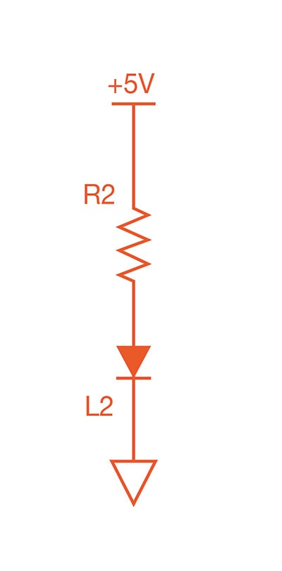
Figure 2: Biasing an LED
To bias the LTST-C171GKT to 5 mA from a 5 V source, we would look at the current-voltage curve, and see that the forward voltage is 2 V at 5 mA. We then apply Ohm’s law:
R=(Vs-Vf)/I=(5-2)/5mA=600 ohms
From the normalized luminosity versus the current plot, we expect about 25% of the typical datasheet brightness when biasing the LED with 5 mA; 25% of the typical value (12 mcd) is 3 mcd.
Care should be taken to bias the LED with a lower current if the LED will be operating in an environment with a high ambient temperature. Reference the forward-current derating curve in the datasheet. An example is shown in figure 3. The LTST-C171GKT is rated for 30 mA up to 50 C. Above 50 C, the recommended bias current is lower.

Figure 3: Forward current derating curve
Image Source: LTST-C171GKT
The driver must also be able to handle the current. Don’t try to drive more current than the driver pin is rated for. If the current is low, a microcontroller pin can sink the LED current directly, as seen in figure 4.
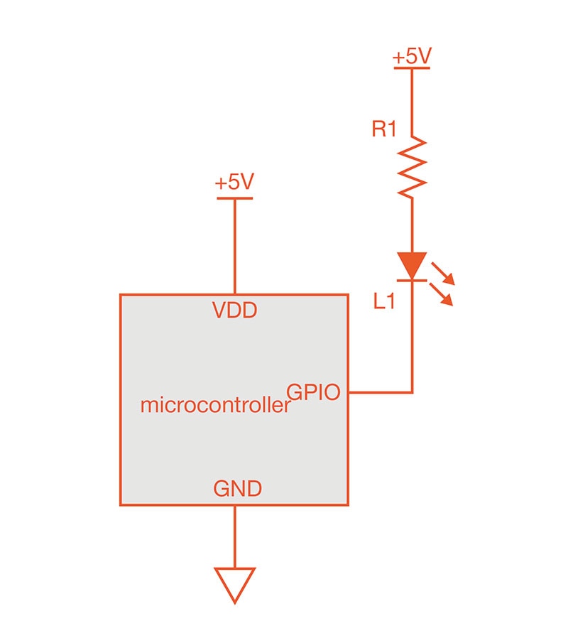
Figure 4: A microcontroller sinks LED current
If the microcontroller pin cannot sink enough current, a MOSFET can be used to sink the LED current. See figure 5.
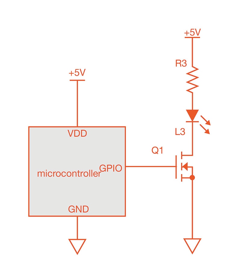
Figure 5: A MOSFET sinks LED current
An LED’s brightness can be dynamically changed (dimmed or brightened) using pulse-width modulation (PWM). In this application, the duty cycle is varied to control the average LED current. If dimming is intended, the driver should be switched at a rate the human eye cannot detect—100 Hz or faster should be sufficient. If blinking is intended instead of dimming, use a lower frequency.
When using PWM to drive an LED, the current limiting resistor can be resized. LEDs have another current rating, the peak forward current rating. This rating is typically the maximum current that an LED can sink for a brief period of time without overheating. For example, the LTST-C171GKT is rated for 120 mA if the duty cycle is 10% or less, with a maximum pulse width of 0.1 ms. This corresponds to 10% duty cycle at a 1 kHz or higher frequency. The resistor can be resized to allow the maximum peak current to flow. Note that the LED temperature will rise and fall with the current pulses. The LED peak temperature will be higher than when running at a longer duty cycle with a higher value resistor.
LEDs do generate heat in the amount of P=V*I. This causes the LED to get hot, so the brighter you run an LED, the hotter it will get. If the power is enough to cause a significant temperature rise, then the LED will require heatsinking. If the power is small, adding copper to the PCB may be enough. The datasheet may have layout recommendations.
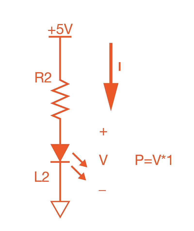
Figure 6: LEDs generate heat according to their brightness.
Have questions or comments? Continue the conversation on TechForum, DigiKey's online community and technical resource.


