Mastering Verilog Syntax and Data types: Part 4 of our Verilog Journey
2024-02-23 | By DWARAKAN RAMANATHAN
Introduction:
Welcome to our guide on Verilog syntax and data types. Whether you're new to digital design or a seasoned pro, this blog will unlock the power of Verilog's language, from intricate digital logic to complex hardware modeling. Let's embark on this journey to Verilog mastery!
Syntax:
In Verilog, syntax refers to the set of rules and conventions that govern how you write and structure your Verilog code. It defines the correct way to represent digital logic, describe hardware components, and specify the behavior of a digital system. Understanding and adhering to Verilog syntax is essential for creating valid and functional designs. Here are some key aspects of Verilog syntax:
Module Declaration: A Verilog design typically starts with the declaration of one or more modules. Modules encapsulate different parts of the design and define their inputs, outputs, and internal logic.
module my_module ( input wire a, input wire b, output wire y );
- Data Types: Verilog supports various data types, including wire, reg, and integer, among others. These data types define how signals are stored and manipulated within the design.
wire a; // Continuous signal reg b; // Register (sequential logic) integer count; // Integer variable
- Operators: Verilog provides a range of operators for performing logical, arithmetic, and bitwise operations. These operators are used to define the behavior of digital circuits.
assign y = a & b; // Logical AND assign sum = a + b; // Addition
- Statements and Blocks: Verilog code consists of statements and blocks. Statements represent actions or operations, while blocks group statements together. Common blocks include always and begin/end blocks.
always @(posedge clock) begin if (reset) begin count <= 0; end else begin count <= count + 1; end end
- Conditional and Looping Constructs: Verilog includes if-else statements and loop constructs like for and while for conditional logic and iteration.
if (a == b) begin // Perform an action end for (i = 0; i < 8; i = i + 1) begin // Loop through code end
- Comments: Comments in Verilog are used to provide explanations and descriptions within the code. They are preceded by double slashes (//) for single-line comments or enclosed within /* */ for multi-line comments.
// This is a single-line comment /* This is a multi-line comment */
- Hierarchy: Verilog allows for hierarchical design, where modules can be instantiated within other modules to create complex systems. This is achieved using instantiation statements.
my_module inst1 ( .a(input_a), .b(input_b), .y(output_y) );
Understanding and following Verilog syntax is crucial to writing valid and functional digital designs. It ensures that your code accurately represents the desired behavior of the digital circuit and can be synthesized into actual hardware.
Keywords:
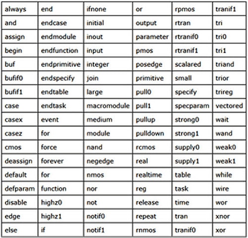
Verilog is a hardware description language (HDL) used for modeling and designing digital circuits. While Verilog doesn't have traditional "keywords" in the same way that programming languages do, it does have a set of reserved words and system tasks/functions that have specific meanings within the language. These words and tasks/functions are essential for writing Verilog code correctly.
Here are some of the most commonly used reserved words and system tasks/functions in Verilog:

Data types:
In Verilog, data types define how data is stored and manipulated within the design. They determine the behavior of signals, registers, and variables in the digital circuit. Verilog provides several data types to accommodate different types of data and hardware modeling requirements. Here are some common Verilog data types:
- Wire (net):
- wire: Wires are continuous signals that represent connections between different parts of the circuit. They are used for data flow and interconnecting gates. Wires cannot store values.
wire a; // Continuous signal 'a'
- Register:
- reg: Registers are used to store and represent data in sequential logic elements, such as flip-flops. They can store values and are primarily used for state-holding elements.
reg b; // Register 'b'
- Integer:
- integer: Integer data types are used to represent signed integer values. They are commonly used for indexing and loop counters.
integer count; // Integer variable 'count'
- Real:
- real: Real data types are used to represent real (floating-point) values. They are less common in hardware modeling but may be used for certain calculations or simulations.
real voltage; // Real variable 'voltage'
- Time:
- time: Time data types represent time values in simulation. They are used for specifying delays, timing constraints, and simulation durations.
time delay; // Time variable 'delay'
- Parameter:
- parameter: Parameters are constants that can be defined at the module level. They allow you to set configurable values for the design.
parameter WIDTH = 8; // Parameter 'WIDTH' with a default value of 8
- Enum (Enumeration):
- Enums allow you to define a set of symbolic values, which can make the code more readable and maintainable.
typedef enum logic [1:0] {IDLE, RUNNING, DONE} state_t;
state_t current_state;
- Array:
- Verilog supports arrays for organizing data elements of the same type into a collection. Arrays can be one-dimensional or multi-dimensional.
reg [7:0] memory [1023:0]; // 1KB memory array with 8-bit data elements
These are some of the common data types used in Verilog. The choice of datatype depends on the specific requirements of your digital design, including whether you need continuous signals (wires), registers for sequential logic, or other data types for specialized purposes.


 中国
中国