The Basics of the Controller Area Network (CAN bus) and its Use in Automotive Applications
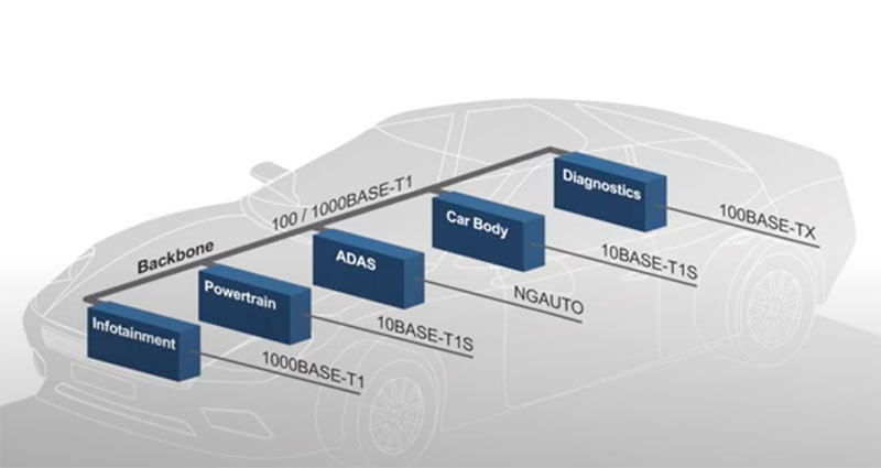
In-vehicle networks (IVNs) allow microcontrollers and engine control unit (ECU) processors to communicate with sensors, actuators, indicators, displays, and each other. The network bandwidth for IVNs depends on the function being supported. Typically basic body and comfort applications work fine with very low bus bandwidth, power-train and chassis applications require a little more bandwidth, safety features use medium bandwidth, infotainment applications use high bandwidth, while advanced driver assistance systems (ADAS) require very high bandwidth.
Also, IVNs can use multiple network architectures, each matched with a group of functional needs. One of the classic IVNs is the Controller Area Network or CAN bus. Let’s take a look at it, and some example CAN bus transceivers from Texas Instruments.
CAN bus capabilities and structure
CAN has been around for about thirty years and continues to evolve. The classic CAN bus is described in the ISO11898 standard. It supports data rates of up to 1 megabit per second (Mbps) and handles medium bandwidth requirements.
The bus routing for a typical vehicle involves a great many connections. Figure 1 shows the large number of connections typical of modern vehicles. In this example, the CAN bus is linked to a lower-speed, local interconnect network (LIN) that operates at data rates of up to 20 kilobits per second (kbps), and is cost-effective for low-bandwidth needs.
 Figure 1: The data bus connections in a typical vehicle implemented with CAN and LIN network elements. (Image source: Texas Instruments)
The high cost and weight of a wiring harness in a vehicle means the implications of a given network configuration must be given serious consideration upfront. The bus configuration in Figure 1 is very cost-effective and efficient. Rather than wire each sensor and actuator to a controller, the network routes multiple connections via simpler wired connections. The LIN bus uses a single wire for communications, and the CAN bus supports higher speeds using a single twisted pair.
As mentioned, the CAN bus, like all active networks, evolves continuously to meet the needs of the industry. CAN Flexible Data Rate (CAN FD) increases the data rate to 5 Mbps. The latest CAN standard is CAN Extra Long (CAN XL) and supports data rates of up to 10 Mbps or more. CAN FD and CAN XL are backward compatible with classic CAN.
The physical layer wiring for the CAN network consists of twisted pair wiring between CAN nodes, as shown in Figure 2.
 Figure 2: The CAN bus uses terminated, twisted pair wiring, and nodes are drop connected. Each node has a CAN transceiver and a microcontroller unit (MCU) with a CAN controller function. (Image source: Texas Instruments)
The bus topology wiring of the CAN network requires 120 ohm (Ω) terminations at both ends of the bus to minimize reflections. Stubs—unterminated open connections—should be minimized. Bus rates depend on the CAN implementation and are affected by the length of the network. The longer the network, the lower the maximum data rate it can sustain. The 1 Mbps rated data rate is for a network length of 40 meters (m) or less.
Communication across a CAN network relies on differential signaling using the two wires in the twisted pair designated CANH and CANL (Figure 3). The CAN transceiver driver is required to achieve a 1.5 volt differential signal across the 60 Ω differential load of the terminated twisted pair. The signal levels are referred to as dominant and recessive. The dominant or ‘1’ level has a differential voltage level greater than or equal to 0.9 volts. The recessive or ‘0’ level has a differential voltage of less than 0.5 volts.
 Figure 3: Shown are the differential signal definitions for the CAN bus CANH and CANL conductors. (Image source: Texas Instruments)
The bus driver is capable of actively driving the bus to the dominant state, while the return to the recessive state depends on resistive discharge through the terminations. This accounts for the shorter rise time when transitioning from the recessive to the dominant state. It also allows a dominant bit to overwrite a recessive bit state. This feature is used for acknowledgment and bus arbitration.
The twisted pair transmission lines have a propagation delay of 5 nanoseconds per meter (ns/m). CAN controllers are configured for the propagation delays of the network to which they are coupled, so this propagation delay information is needed to ensure correct bus arbitration and prioritization.
CAN transceivers, which physically drive the bus, are available in 8 pin and 14 pin versions. The Texas Instruments TCAN1042GDQ1 is an 8-pin version that supports CAN FD. Conveniently, Texas Instruments uses a common pin mapping for the top eight pins on both the 8 and 14 pin versions, allowing drop-in replacement. The transceiver is compatible with a Texas Instruments TMS5703137CGWTQEP microcontroller (MCU), which has three CAN controllers available (Figure 4).
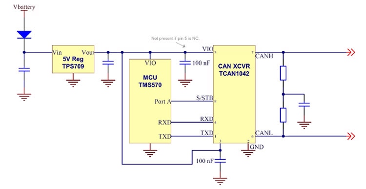 Figure 4: A typical 8-pin transceiver application with the transceiver connected to the transmit (TXD) and receive (RXD) ports of an MCU which includes multiple CAN bus controllers. (Image source: Texas Instruments)
14 pin CAN transceivers have additional functions, including auxiliary power buses and extended low-power and sleep modes.
The Texas Instruments TCAN1043GDRQ1 is a 14 pin CAN transceiver that supports full 5 Mbps operation under CAN FD. It is also compatible with the TMS5703137CGWTQEP MCU (Figure 5).
 Figure 5: A typical application of a 14 pin CAN transceiver incorporating extended low-power and sleep modes controlled via the extra six pins. (Image source: Texas Instruments)
CAN protocol
The CAN bus follows a standardized protocol that allows the network to address data and commands where needed (Figure 6).
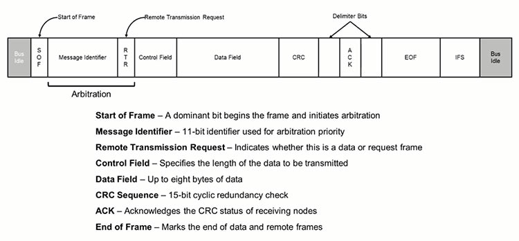 Figure 6: The CAN protocol provides a structure for transferring data across the bus and verifying that it is received. It also provides error checking. (Image source: Texas Instruments)
Between transmissions, the bus is in an idle state at the recessive voltage level. The start of the transmission frame (SOF) is marked by the transmission of a dominant bit. A message identifier in the next field is followed by a remote transmission request (RTR)—which indicates whether the frame contains data or is requesting data. These two fields are used to establish message priority and arbitrate access to the bus.
The Control Field contains the length of the following data field. The data field can have up to eight data bytes in classic CAN.
If data is being transmitted (data frame), then the data field is followed by the cyclic redundancy check (CRC) which is used to check for transmission errors. At this point, the driver puts the bus into a recessive state so the receiver can acknowledge (ACK) successful receipt by asserting a dominant state. The ACK bit is surrounded by delimiter bits on each side. After the ACK bit, the controller sends a seven-bit end-of-frame (EOF) message followed by a seven-bit interframe spacing, marking the minimum time before another frame can be transmitted.
If the bit sequence contains five or more bits of the same state, then the controller will insert a stuff bit of the opposite state to ensure that there are sufficient edges in the signal to maintain synchronization. These stuff bits are removed by the receiver so that the data content is correct. After the CRC field, bit stuffing is deactivated to ensure that the ACK and EOF fields do not show stuff bits.
Differences between CAN and CAN FD
We already know that CAN FD operates at data rates of up to 5 Mbps compared to the 1 Mbps maximum data rate for CAN. This improvement is accomplished by increasing the data clock rate selectively; hence the name CAN FD (Figure 7).
In CAN FD, the clock rate during the data and CRC fields is increased so that twice as much data can be transmitted in the same period of time, or the same amount of data can be transmitted in half the time, giving CAN FD a greater bandwidth. The rest of the protocol timing remains the same. This arrangement is backward compatible, and CAN FD devices can operate in a CAN environment. Additionally, CAN FD supports data fields as large as 64 bytes compared to the eight-byte limit of CAN, which also increases the data rate.
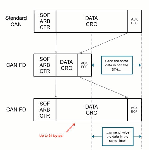 Figure 7: CAN FD uses a variable data rate in the data and CRC frames to increase the overall data rate of the transfer. (Image source: Texas Instruments)
What’s ahead for CAN bus?
The high end of the in-vehicle network spectrum is occupied by 100BASE-T and 1000BASE-T Ethernet networks. There is quite a gap between lower-speed buses like CAN FD at 5 Mbps and these higher-speed buses. Currently, there are two contenders under development in the 10 Mbps space, namely 10BASE-T1S and CAN XL.
CAN XL increases the data rate and data payload size. The data payload length is increased to a maximum of 2048 bytes, accounting for the name “extra long.” CAN XL still maintains backward compatibility with CAN and CAN FD for operation at lower speeds.
Conclusion
The CAN bus two-wire twisted pair interface has been around for many years and continues to grow to meet the expanding array of automobile connectivity requirements. It can be used by itself or to complement single-wire networks like LIN to minimize overall weight and cost. It is supported by a variety of classic and CAN FD transceivers from companies such as Texas Instruments.

Have questions or comments? Continue the conversation on TechForum, Digi-Key's online community and technical resource.
Visit TechForum


