Cutting That Whip Antenna Down to Size
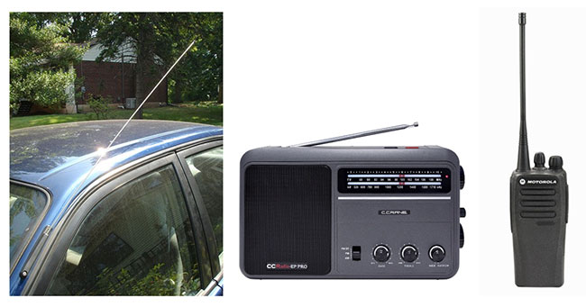
The whip antenna, formally known as the monopole or “Marconi” antenna, is a classic, widely used basic design. It’s as simple as an antenna can be, has been widely studied in theory, and is used in practice in many variations on cars, portable radios, and broadcast towers, just to mention a few (Figure 1). It’s relatively easy to build one that’s rugged enough for mobile use, and it can adapt to the application requirements.
 Figure 1: The monopole antenna is widely used in applications such as automobiles (left),; the FM band of portable AM/FM radios (center),; and specialized walkie-talkies (right). (Image sources: Wikipedia, C.Crane, and Delmmar Communications Corp.)
The principle of the monopole antenna is simple. It has a single driven element located on top that is insulated from an infinite ground plane. This ground plane can be actual ground or a large, conducting surface. The monopole can be considered a variation of the also widely used dipole antenna, but with the monopole, one side of the dipole is now the ground plane (Figure 2).
 Figure 2: The monopole has a single driven element atop a ground plane (a), and can be analyzed as a dipole where one arm is driven while the ground plane creates an electric-field mirror image (b). (Image source: Flightradar24)
The ground plane enables the monopole antenna to be the electrical equivalent of a dipole antenna, where the ground plane replaces the lower half with an imaging principle similar to creating an optical image through a mirror.
Making it shorter
Two factors that affect the practical performance of the theoretical monopole antenna: the non-ideal nature of the ground plane, and the physical dimensions and construction of the radiating monopole itself. In most applications, there is not much that can be done about the ground plane, as it is usually defined by the installation, such as the surface of a car or the enclosure of a handheld radio.
The situation for the monopole element is different than it is for the ground plane. To be an effective radiator of electromagnetic energy at the operating frequency, the length of the monopole is critical, ideally one-quarter of the operating wavelength, lambda (λ). For this reason, monopoles are sometimes called “quarter-wave” antennas. An ideal quarter-wave monopole with an ideal ground plane has an input impedance of just under 40 ohms (Ω).
Going through the math, an ideal quarter-wavelength is 75 meters (m) at 1 megahertz (MHz), 7.5 m at 10 MHz, 75 centimeters (cm) at 100 MHz, and 7.5 centimeters at 1 gigahertz (GHz). In practice, it is often impractical to use the ideal length—especially at the lower frequencies. A quarter-length antenna for the FM broadcast band (88 to 108 MHz) is practical at approximately 75 cm (30 inches), but one for the AM band (550 kilohertz (kHz) to 1.6 MHz) is impractical as it would be 100 times that length.
Fortunately, the length and construction materials of the monopole provide many degrees of design freedom and flexibility, in contrast to the constraints of the available ground plane. The obvious correction to unacceptable length is to shorten the monopole, but doing so has RF consequences; as it is shortened, its impedance becomes capacitive, and it is a less-effective radiator. There are also changes to radiation pattern, bandwidth, and other parameters. The most common way to compensate for these changes is to add an inductive loading coil to the antenna. While this seems simple enough, there are many ways to add this inductive element, and each approach brings tradeoffs with respect to antenna performance.
Therefore, it’s not enough to calculate how much inductance is needed and just add it. How and where this inductance is added makes a big difference in its actual performance as compared to theory.
Compensation for shortening
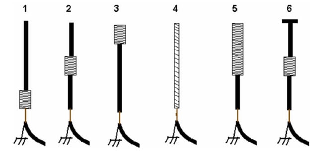
There are multiple ways to add the loading coil inductance, and the actual inductance value is a function of placement to some extent (Figure 3). The loading coil is often implemented as part of the monopole rather than as a distinct, separate element, just as a straight wire is coiled to create an inductor. Using the monopole element this way is generally less costly and more rugged than having a discrete inductive component connected to the antenna.
 Figure 3: The inductor used to compensate for the capacitive impedance of the shortened monopole antenna can be placed in many ways. (Image source: webclass.org)
Among the approaches are:
Base loading: A series inductance is located at the antenna base. This requires a relatively smaller inductance value but does not increase radiation effectiveness as much as other locations.
Center loading: Uses a somewhat larger inductance but increases radiation effectiveness.
Top loading: Offers the best improvement in radiation efficiency but needs an even larger inductor, which is mechanically challenging for obvious reasons.
Helical or continuous loading: This provides a good compromise as it distributes the inductance and also provides a strong, yet flexible antenna; many of the so-called “rubber ducky” whip antennas on portable walkie-talkie radios use this technique.
Half-and-half loading: Half the antenna is made as a loading coil and half is not; whether the top or bottom half is used has a significant impact on performance characteristics.
Capacitive top loading: Combines a center loading coil with a flat capacitive element at the top; while this seems counterproductive, it increases radiation resistance, efficiency, and bandwidth.
In short, there are many options associated with a desired antenna design and actual physical implementation. Keep in mind that with non-ideal antennas—and they all are non-ideal in some way—many secondary factors that affect the actual performance, including the thickness of the antenna conductor wire or tubing and any protective coating it may have. Advanced electromagnetic field analysis tools can do a very good job of modeling performance and factoring these into the design, but field tests are still needed.
Make or buy?
It is possible to build your own antenna, and doing so may make sense for a unique custom design or a personal project. However, making even the simple monopole antenna for use at scale requires sophistication in design, materials selection, fabrication, and evaluation. Fortunately, there are thousands of standard antennas available from vendors that are ready to use that come with detailed performance and operational specifications, as well as technical support.
Two very different examples of 915 MHz antennas from Taoglas Limited illustrate the wide span of options. The HA.31.A is a simple-looking helical whip antenna measuring 10.7 millimeters (mm) long with a diameter of 10.2 mm (Figure 4). Made of copper alloy, it is mechanically sturdy and designed to be soldered directly to the circuit board embedded within a device, such as a smart meter, security system, remote asset monitor, or other wireless communication devices.
 Figure 4: The HA.31.A 915 MHz “bare- bones” helical monopole antenna is just 10.7 mm long and is designed for protected pc board mounting in embedded devices. (Image source: Taoglas)
The HA.31.A features a 3 decibel (dB) bandwidth of 902 to 928 MHz, offers 2 dB isotropic (dBi) peak gain, and 68% efficiency at 915 MHz on a 126.8 × 80.1 mm ground plane.
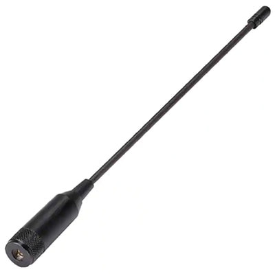
In contrast, the FW.95.B.SMA.M is a more traditional-looking 226 mm, base-loaded whip antenna designed for outdoor use (IP65 dust and water-resistant), complete with an SMA type (M) straight connector at its base (Figure 5).
 Figure 5: The Taoglas FW.95.B.SMA.M is a 915 -MHz ruggedized helical whip antenna which can be used in environmentally harsh applications. (Image source: Taoglas)
The diameter at its base is 16 mm, while the whip section has a 6 mm diameter.
Its efficiency is over 60%, with a peak gain of better than 2.71 dBi at 915 MHz on a 30 × 30 centimeter ground plane. This rugged antenna was developed for monitoring systems including weather, motion/vibration sensors, and pollutants.
Conclusion
The theory and design of a basic monopole whip antenna is straightforward in principle. However, the actual implementation involves many fabrication considerations, along with subtle corrections and adjustments for real-world, non-ideal considerations. Fortunately, a wide selection of standard antennas is available from many vendors to meet the priorities and constraints of nearly every application.
Related Content
1: Beyond Wires: Antennas Evolve and Adapt to Meet Demanding Wireless Requirements
https://www.digikey.com/en/blog/beyond-wires-antennas-evolve-and-adapt
2: Understanding Antenna Specifications and Operation, Part 1
https://www.digikey.com/en/articles/understanding-antenna-specifications-and-operation
3: Understanding Antenna Specifications and Operation, Part 2
https://www.digikey.com/en/articles/understanding-antenna-specifications-and-operation-part-2
4: Selecting Antennas for Embedded Designs
https://www.digikey.com/en/articles/selecting-antennas-for-embedded-designs
5: Antenna Selection Depends on Many Factors
https://www.digikey.com/en/articles/antenna-selection-depends-on-many-factors
6: Applying Chip and Patch Antennas to Solve Diversity and Multiband RF Issues
https://www.digikey.com/en/articles/applying-chip-patch-antennas-diversity-multiband-rf-issues
References
Everything RF, “What is the difference between a monopole and dipole antenna?”
RF Wireless World, “Whip antenna calculator | monopole antenna calculator”
Silicon Labs, “Whip antenna parameters”
Science Direct, “Monopole Antenna”
University of Toronto, “Image Theory/Monopoles”
Wikipedia, “Whip antenna”
Electrical Engineering Department, IIT Bombay, “Monopole Antennas”
66Pacific, “Coil-Shortened Vertical Antenna Calculator”
AntennaX, “Loading Short Antennas”
Antenna-theory.com, “The Monopole Antenna”

Have questions or comments? Continue the conversation on TechForum, Digi-Key's online community and technical resource.
Visit TechForum


