Antenna Selection Depends on Many Factors
投稿人:电子产品
2011-12-01
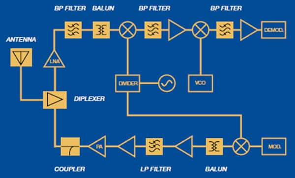
Today, just about every mobile device has at least one internal antenna, with many devices sporting three or more to provide wireless communications for functions such as GPS, Wi-Fi, Bluetooth, ZigBee and of course, the cell phone (CDMA, GSM, 3G, LTE 4G, WiMAX, etc.). In a typical single-channel system, the transmit and receive paths are multiplexed to the antenna (Figure 1). However, it is also possible to use multiple antennas on the same receiver to leverage “antenna diversity” by which signal processing selects the stronger signal to improve reception. Additionally, the use of MIMO (multiple-input/multiple output) radios will add even more antennas to the mix, with each receive/transmit channel sporting its own antenna (for example, a 2 x 2 MIMO system would have four antennas).
Although antennas are an essential element in almost every portable device, the selection of the antenna is often left to the end of the system design, and designers end up trying to fit the antenna or antenna array into whatever space is available. In some systems, the antennas are part of the traces etched on system’s printed-circuit board (PCB), or mounted on the PCB as a chip component (Figure 2). In other designs (Figure 3) the antenna is part of the RF module’s package, and in yet other designs, the antenna is part of the system housing (like the antenna embedded in the case of Apple’s iPhone 4).

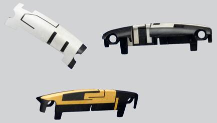
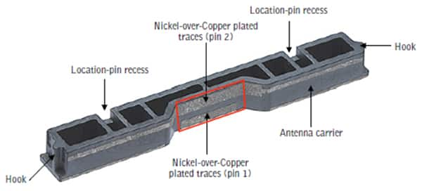
To deposit the antennas on plastic, Molex leverages a technique it calls laser-direct structuring (LDS), which links a 3D laser system to their computer automated design (CAD) software to transfer the antenna design directly from the CAD system onto the plastic carrier.
Thus, selecting the best antenna requires more than just a set of RF specifications. Physical size is an important factor, as is the potential interference between antennas when multiple radios are simultaneously active in the portable device. Also, when designing the antennas into your system, you will have to consider factors such as orientation, impedance matching of the antenna to the micro-strip line on the PCB, the PCB layout (taking into account other components on the PCB and how they might interfere with the RF signals), the enclosure material, adjacent metal components, and other factors. All of these aspects could cause drops in the signal strength such that when combined, the system is left with no received signal or a significant loss in transmitted power.
For example, for antennas that are integrated on the PCB, the geometry of the ground plane affects the impedance of the antenna. Thus the length of the antenna should be tuned according to the size and shape of the ground plane. The antenna shape can be circular, square, rectangular, or elliptical and is etched on one side of the PCB; the other side of the PCB should be bare in the region of the antenna – no ground plane or circuit traces should run underneath the antenna. On the transmit path, the power amplifier connects to the antenna (either directly or through a matching network). The other end of the antenna is typically open and the antenna resembles a whip or monopole antenna. Although printed antennas save money, the drawback in using them is that their characteristics depend on the manufacturing tolerances of the board material and traces. There are surface-mount antennas available with much more repeatable characteristics, and they should be considered when consistency of the antenna design is important.
The antenna radiation pattern is one key aspect that will help determine how the radiated energy is released in free space and the antenna configuration required to implement the pattern. In most portable, handheld applications, omnidirectional antennas are preferred over high-gain antennas since the high-gain antennas are directional – they deliver good performance in one direction and compromised performance in other directions.
Antennas can also come as a tiny PCB that can be mounted on the main system PCB. Sometimes referred to as a paper-clip antenna, it typically consists of a wire or flat strip of metal that connects to the PCB then follows a similar layout as the etched PCB antenna. The impedance of such raised-strip antennas is similar to the impedance of the etched PCB antennas.
The shortest resonant wavelength of a typical antenna is a half-wavelength, although quarter-wavelength monopole antennas such as the chip antennas from Johanson can reduce the space required by the antenna. If used in conjunction with an appropriate transmission-line feed structure and a suitable ground plane, the antenna can perform like a half-wavelength dipole system. The ground plane forms the second quarter-wavelength element to complete the half-wavelength dipole.
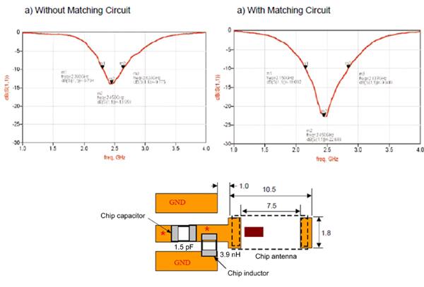
Impedance matching for antennas must be done to optimize the antenna performance. To match an antenna to the 50 Ω impedance of the micro stripline, external components “tune” the antenna for optimum response at the operating frequency bandwidth by maximizing the power transfer to the antenna. For example, the Johanson Technology model 2450AT45A100 chip antenna operates at 2.45 GHz, requires a 1.5 pF series capacitor and a 3.9 nH shunt inductor (Figure 4). The accompanying graphs in Figure 4 show the performance of the antenna, with and without the tuning components. The optimized result shows a significant improvement in return loss (improved VSWR). The actual component values, however, will vary for each application, depending on the PCB material, the board and trace thickness, and other factors.
In general, to select the best antenna, designers should address the following specifications as a starting point: frequency, bandwidth, radiation pattern (peak gain and average gain), and size. Often the frequency band will determine the general size of the antenna or, if the system will operate across multiple frequency bands, the multiple antennas that must be incorporated into the system.
Companies such as Johanson Technology, Antenova, TDK Corporation, Molex, and many others offer chip antennas that can be surface-mounted on the radio circuit board. These chip antennas come in various sizes, with a wide range of gain values and return-loss values, depending on the frequency range desired for the antenna. Antennas can also be laser etched on the various plastic portions of the case that houses the radio circuitry. For instance, the antenna for a mobile TV application (Figure 5) prints the antenna pattern onto a plastic carrier that is part of the mobile product’s case.
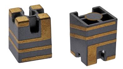
Antennas come in a wide variety of shapes and sizes to meet almost every application requirement. However, just about every antenna vendor will also design custom solutions if the off-the-shelf antennas do not meet your performance requirements.
免责声明:各个作者和/或论坛参与者在本网站发表的观点、看法和意见不代表 DigiKey 的观点、看法和意见,也不代表 DigiKey 官方政策。


