Selecting Antennas for Embedded Designs
投稿人:Convergence Promotions LLC
2012-11-08
The wide range of RF protocol choices available to embedded developers makes the already complex choice of antennas that much more difficult. Gain, directionality, and bandwidth all represent serious trade-offs that dictate the choice of antennas – dipole, monopole, patch, flat bar, center-fed, end-fed. The choices are seemingly endless. So-called smart antennas make the choice that much more complex, as does the fact that the layout of your PCB will almost guarantee that the antenna you choose will not work as advertised.
This article will examine basic antenna design parameters and recommend which types of antennas make the most sense for the most popular embedded wireless applications. It will also address some design considerations that can have a major effect on how your antenna works in practice. You don’t need to know how to design antennas in order to know how to design with them.
Theoretically speaking
An antenna is a device that converts electric currents into electromagnetic waves to transmit information and the reverse to receive it. You can think of an antenna as a complex RLC network. If the antenna is too long, it will display a predominantly inductive reactance. If it is too short, it will present to the PA as a primarily capacitive reactance; at resonance, these reactances will cancel each other out and the impedance will be purely resistive (see Figure 1).
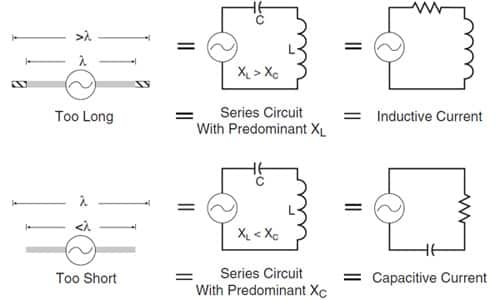
Figure 1: Effect of mismatch between antenna length and operating frequency (Courtesy of Linx Technologies).
The length of the antenna is determined by its intended operating frequency, where wavelength is determined by the following formula:

where:
λ = wavelength in meters
c = speed of light (299,792,458 meters per second)
f = frequency in Hz
So a full wave antenna for 916 MHz would be 0.33 meters (1.08 feet). A full wave antenna for 2.4 GHz would be 0.13 meters (0.41 feet). Since there is clearly not a 12-inch antenna in your cell phone for making calls or a five-inch antenna for Wi-Fi, some compromises are clearly at work.
Resonance occurs at whole number multiples or fractions of the wavelength of the antenna, though a half-wave is the shortest resonant length of an antenna. However, you can get around that limitation, since a ¼-wave monopole antenna can radiate against a ground plane – usually a metal layer on a PCB – which then acts as the missing half of a half-wave dipole. Quarter wave monopoles are by far the most popular antennas used in portable wireless devices. Now your 916 MHz antenna is down to three inches (before presumably coiling it up) and your Wi-Fi loop a mere 1¼ inches.
Care and feeding of antennas
The feed point on a resonant center-fed half-wave dipole occurs at the point of minimum voltage and maximum current, which enables the most efficient power transfer from the transmitter (see Figure 2). All things being equal, the PA is looking into a 73 Ω resistive load for a dipole or a 36.5 Ω load for a monopole.
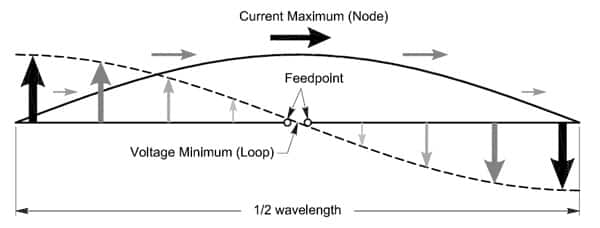
Figure 2: Current and voltage distribution on a half-wave dipole.
In practice of course, things are rarely that simple – at least without further engineering. If the feed point is moved off center, or if the antenna is operated off of its resonant frequency, or if for any reason the antenna is not perfectly matched to a source impedance, then a voltage is reflected back toward the load, forming standing waves on the transmission line, thereby detracting from the effective radiated power.
The voltage standing wave ratio (VSWR) is a measure of how well an antenna is matched to its source impedance. A perfect match would be 1:1, with a VSWR of 2:1 often being used to specify the useful bandwidth of an antenna. At a VSWR of 2:1, 88.9 percent of the power sent to the antenna is radiated into space, with 11.1 percent reflected back to the source and generally lost as heat in the PA and the transmission line. VSWRs of over 2:1 can be accommodated with antenna tuners, but that adds to the cost and complexity of the device.
To minimize VSWR, the characteristic impedance of the transmission line must be matched to both the PA and the antenna. Unless you buy an antenna module complete with a length of co-ax and connector, this is no simple design task. PCB traces between the PA and antenna may simply act as radiating elements unless they're carefully routed and matched. Even then, the chances of their being detuned by nearby devices on the board or picking up EMI from digital sources represents a design challenge that needs to be carefully studied. We’ll get back to that after the next section.
Polarization, directivity, and gain
An electromagnetic wave has two components: an electrical field and magnetic field that are at right angles to each other. By convention, the orientation of the electrical field to the earth’s surface determines its polarization. Polarization can be horizontal, vertical, or even circular. All that matters is that both the transmitting and receiving antennas are oriented in the same plane, otherwise a considerable amount of energy can be lost due to the receiving antenna intercepting only a small portion of the electrical field. In the case of portable handheld devices, cross polarization can be a considerable problem that is increasingly being addressed by the use of multiple “smart” antennas, though that technology is beyond the scope of this article.
You cannot get more power out of an antenna than you put into it, but you can greatly increase the gain in a given direction by increasing its directivity (see Figure 3). Antenna gain is typically measured against a theoretical isotropic antenna in free space that radiates equally in all directions (dBi). Occasionally you will see gain measured against a dipole, in which case the gain is stated as dBd. A standard half-wave dipole has about 2.2 dB gain over isotropic.
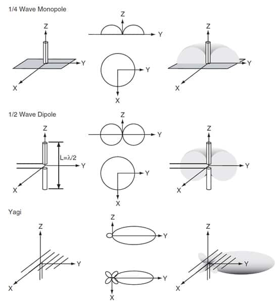
Figure 3: Antenna radiation patterns (Courtesy of Linx Technologies).
When both the transmitting and receiving devices will remain stationary, antenna gain can be greatly increased by adding additional passive elements in front of and behind a dipole – elements known as directors and reflectors respectively. For example, the Linx Technologies ANT-DB1-LOW-LP-RM-01-N tri-band log periodic antenna delivers 8.5 to 9 dBi on the 824 to 960 MHz, 1.71 to 2.17 GHz, and 2.4 to 2.48 GHz bands. RF Solutions makes the ANT-GSM-YAG11, a dual-band Yagi with 11 dB gain at both 900 MHz and 1.8 GHz.
Ground plane effects
Since the ground plane, or counterpoise, supplies the missing half of a quarter-wave monopole antenna, its size, orientation, and layout all have a major impact on the effectiveness of your design. Anything less than a full-wave counterpoise – something that is impractical in portable designs – has a significant effect on the impedance, resonant frequency, and radiation pattern of the antenna.
The counterpoise for the small antennas used in embedded devices is typically the copper layer on a PCB that also serves as the circuit ground. An antenna mounted perpendicular to the ground plane will have an omnidirectional radiation pattern in the plane perpendicular to the antenna – creating a classic vertical antenna – though moving it to one edge of the board will create a null in the opposite direction. On the other hand, mounting a monopole antenna in the same plane as the board creates a classic bipolar dipole radiation pattern.
In either case, it is important that the ground plane be at least one quarter wavelength or the performance of the antenna system will be seriously compromised. Try to run traces away from the antenna, not intersecting the ground plane within one quarter wavelength of the antenna. Also, mount the PA as close as possible to the antenna to minimize any transmission line issues.
It is important that the copper ground plane not be so complex – either cut up with traces or divided between layers and connected by vias – which cannot serve as an effective counterpoise for the antenna. As far as possible, try to keep the ground plane intact and leave large areas of copper between the antenna and other circuit components.
Antenna types
There are dozens of different types of antennas, many of them quite specialized. In this section, we will discuss those most commonly used in embedded wireless devices.
Whip antennas
Devices designed for wireless machine-to-machine (M2M) communications – for example, from a router to your PC – typically use external whip antennas. Whip antennas are generally wideband, not easily detuned, and easily integrated into a wireless design. Being externally mounted, they are commonly used in commercial applications, but rarely any longer in portable designs.
Pulse Electronics’ W1030 (see Figure 4) is a quarter-wave whip antenna designed for WLAN devices. The W1030 exhibits 2.0 dBi gain from 2.4 to 2.5 GHz with a VSWR of less than 2.0 and a nominal impedance of 50 ?, making it well-suited for Wi-Fi, Bluetooth, ZigBee, and industrial applications that use that band.
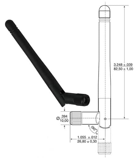
Figure 4: Whip antenna (Courtesy of Pulse Electronics).
Helical antennas
A helical antenna is simply a length of wire that is wound into a coil. The overall length of the wire determines its resonant frequency, but coiling it can greatly reduce its physical size. Helical antennas have a high Q and thus a narrow bandwidth, which generally limits their use to narrowband protocols. In addition, they can be easily detuned by the presence of other objects on the PCB, so designs utilizing them must be thought out and the design laid out with care.
Linx Technologies’ ANT-315-HESM (see Figure 5) is a quarter-wave SMD helical monopole antenna designed for 315 MHz operation. Typical of helical antennas, it has a narrow bandwidth – approximately 10 percent of the center frequency. Being less than a third of the length of a comparable whip antenna, these antennas would be well-suited to small, portable devices except for the fact that they are considerably less efficient than whips. Thus, they make more sense on the tethered transmit side, where you presumably have power to spare, and not in a portable device where you likely won’t. They are, however, very low cost, easily concealed, and rugged.
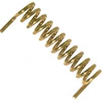
Figure 5: Helical antenna (Courtesy of Linx Technologies).
Planar and chip antennas
Planar and chip antennas are small, pretested, and relatively efficient – offering an attractive “drop-in solution” for RF system designers. They come in a wide range of physical and electrical configurations, only a few of which we can cover here.
Taiyo Yuden’s AH316M245001-T (see Figure 6) is a tiny (3.2 x 1.6 x 0.5 mm) flat bar antenna designed for Wi-Fi and Bluetooth applications in the 2.4 GHz band. It features a peak gain of 1.9 dBi (0.0 dBi average) and a bandwidth of 190 MHz (VSWR less than 2.0) centered on 2.450 GHz. The radiation pattern is essentially bipolar – indicating that it is a dipole – but being of such small size the manufacturer rightly warns that “electrical characteristics vary depending on environment or measurement condition.” Taiyo Yuden has a product training module on DigiKey’s site that explains how their flat bar antennas work.
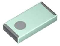
Figure 6: Flat bar antenna (Courtesy of Taiyo Yuden).
Another drop-in option is the mini ceramic loop. Taoglas’ ILA.01 (see Figure 7) is a small (10 x 3.2 x 0.6 mm), highly efficient (70 percent), omnidirectional loop antenna with a center frequency of 915 MH, a bandwidth of 26 MHz, and a gain of 0.9 dBi. Taoglas recommends this antenna for space-constrained M2M applications such as automated meter reading, remote monitoring, healthcare, communications, and RFID. They recommend that this antenna be placed at the center edge of the PCB, since the center frequency will be offset by the presence of other devices as well as the conditions of the ground plane.
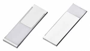
Figure 7: Ceramic loop antenna (Courtesy of Taoglas).
Finally, the flat patch antenna offers good performance in a small form factor. Molex’s 47950 (see Figure 8) is a dual-band Wi-Fi patch antenna that offers 70 percent efficiency in the 5 GHz band and 80 percent at 2.4 GHz. The larger of the devices (15.9 x 35.9 mm) can achieve up to 3.4 dBi from 2.4 to 2.5 GHz and 5.5 dBi from 4.8 to 5.85 GHz, though orientation matters since the bipolar radiation pattern reflects their dipole design. These devices are free of ground plane effects since they mount separately to the device case and connect to the PCB with a micro-coaxial cable. Target applications include Wi-Fi access points, consumer electronics, and telemedicine devices.
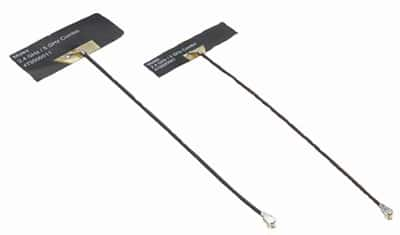
Figure 8: Flat patch antennas (Courtesy of Molex).
PCB trace antennas
The least expensive, most challenging way to incorporate an antenna into your design is to print it directly onto the PCB. While inexpensive, PCB trace antennas are inefficient, sensitive to the presence of nearby components, and difficult to match and tune – not to mention design. They are commonly used in undemanding designs such as garage door openers and car alarms, but there are better, more compact alternatives for more sophisticated designs.
There are, however, both situations and the applications where a prefab PCB antenna works well. For example Laird Technologies makes the MAF94442 (see Figure 9), a quad-band GSM PCB antenna that covers the 850, 900, 1800, and 1900 MHz UMTS bands, all on a single PCB that you can easily add on to your design, assuming you have the room. The 20 mm x 70 mm MAF94442 offers a respectable 2.2 dBi gain at 900 MHz and 3.8 dBi at 2000 MHz. Designed to be mounted separately from the device PCB, the device avoids ground plane considerations and the attendant headaches. Target applications are handheld data devices or access points.
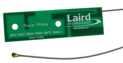
Figure 9: Multiband PCB antenna (Courtesy of Laird Technologies).
Summary
While antenna design is quite complex, antenna selection is considerably less so. DigiKey carries a wide range of antennas, a number of which are likely to be well suited to a given embedded wireless application.

免责声明:各个作者和/或论坛参与者在本网站发表的观点、看法和意见不代表 DigiKey 的观点、看法和意见,也不代表 DigiKey 官方政策。


