制造商零件编号 715
I2C CONTROLLED + KEYPAD SHIELD K
Adafruit Industries LLC
License: See Original Project LCD / TFT Arduino
Courtesy of Adafruit
Guide by Lady Ada
Overview
This new Adafruit shield makes it easy to use a 16x2 Character LCD. We really like the range of LCDs we stock in the shop, such as our classic blue & white as well as the fancy RGB negative and RGB positive.
Unfortunately, these LCDs do require quite a few digital pins, 6 to control the LCD and then perhaps another 3 to control the RGB backlight for a total of 9 pins. That's half of the pins available on a classic Arduino!
With this in mind, we wanted to make it easier for people to get these LCD into their projects. So, we devised a shield that lets you control a 16x2 Character LCD, up to 3 backlight pins AND 5 keypad pins using only the two I2C pins on the Arduino! The best part is you don't really lose those two pins either, since you can use I2C-based sensors, real-time clocks, etc. and have them share the I2C bus. This is a super slick way to add a display without all the wiring hassle.
This shield is perfect for when you want to build a stand-alone project with its own user interface. The 4 directional buttons plus select button allows basic control without having to attach a bulky computer.
The shield is designed for 'classic' Arduino-shaped boards such as the Uno, Metro, etc. But it will also fit "Mega" sized boards because the I2C pins are labeled SCL/SDA.
This used to come as a kit but now comes as an assembled SMT design, so much less soldering is required.
Revision History:
As of May 29, 2024 – The PCB's design has been updated. Now it comes with the buttons, chips and other components already soldered into place. You will still need to solder on the shield headers and the LCD, but it's a lot easier.
Text editor powered by tinymce.
Parts List
As of May 29, 2024 – The PCB's design has been updated. Now it comes with the buttons, chips and other components already soldered into place. You will still need to solder on the shield headers and the LCD, but it's a lot easier.
Rev B:
The shield comes with the board and headers. All other parts are already soldered on for your convenience!
Rev A:
Check to make sure your kit comes with all the parts. Sometimes we make mistakes so double check everything and email support@adafruit.com if you need replacements!
1) Resistors
There is a total of 5 resistors in this kit. For resistors labeled R1 and R2 on the PCB, they are 1/4W 5% 4.7K resistors (Yellow, Violet Red, Gold). For resistors labeled RED and BLUE on the PCB, they are 1/4W 5% 220-ohm resistors (Red, Red, Brown, Gold). For the resistor labeled GREEN on the PCB, it is a 1/4W 5% 330-ohm resistor (Orange Orange Brown Gold).
2) Potentiometer
There is one 10k trim potentiometer. This part will go in the spot labeled Contrast, near the RESET button. Note: The pot may be blue instead of orange.
3) Pushbuttons
There is a total of 6, 6mm tactile switch pushbuttons. These will be used in the UP, DOWN, LEFT, RIGHT, SELECT, and RESET locations on the PCB.
4) i2c Port Expander Chip
There is one of these MCP23017 i2c (16 input/output) port expander chips in the kit. This is how we are able to only use 2 Arduino pins to run the entire LCD and buttons. Click here for more info on this chip.
5) Male Header Pins
There are two strips of 36 male header pins in the kit. These will be used to attach the shield to the Arduino, as well as attach the LCD to the PCB.
6) Printed Circuit Board
There will be one PCB in the kit as shown above.
Additional
You'll want an LCD to place into the shield. This isn't included by default since a lot of people already have LCDs they may want to use. (We do sell these in packs however, so chances are you did get an LCD with your order.)
You can also use 16x2 LCDs or even OLEDs that are the same size that do not have an RGB backlight or have no backlight at all.
We carry Negative type or Positive type LCDs.
Text editor powered by tinymce.
Assembly
As of May 29, 2024, the shield comes with the buttons, chips and other components already soldered into place. You can skip ahead to the Headers section if you have this new version.
Check the kit against the parts list to verify you have all the parts necessary.
Put the printed circuit board into a vise or board holder, heat up your soldering iron and make sure you are ready to go!
Resistors
We'll start with the first resistor R1 - which has yellow, violet, red, gold bands on it. This resistor is part of the interface between the Arduino and the 'port expander' that controls the LCD.
Bend the resistor into a 'staple' and slide it into the slot marked R1 on the PCB. Resistors do not have a direction so you can put it in 'either way' and it'll work fine.
Bend the 'legs' of the resistor out so it sits flat against the PCB and flip it over.
This way the resistor won't fall out while soldering.
With your soldering iron heated up and ready, solder in both leads of the resistor. To do this, heat up the round ring pad and the wire lead at the same time for 2 or 3 seconds, then dip the end of the solder into the heated joint to melt it in.
Then remove the solder and the soldering iron.
Once the soldering is complete, we can clean up by clipping the leads of the resistor. This keeps them from shorting to something else. Use diagonal or flush cutters to clip the wires right above where the solder joint ends.
Since you did so great with the first resistor, we'll place all of the rest now at the same time. R2 is a 4.7K resistor just like R1 (Yellow, Violet, Red Gold) so place that one first.
Next you can do the two 220-ohm resistors RED and BLUE - named because they are the backlight series resistors for the RGB backlights on the LCDs. These resistors are colored Red Red Brown Gold. They look very similar to the 330-ohm resistor so check carefully that you have the red-band ones. Use a multimeter if you can to verify the resistance!
Finally, place the remaining 330-ohm resistor (Orange, Orange, Brown, Gold) into the GREEN spot. The green LED is might brighter than the red or blue in the RGB backlight, so a larger resistor is required to balance it out.
Make sure the resistors all sit nice and flat against the PCB.
Solder the resistors just like you did with the first one.
Clip all the leads.
Buttons
Next up we will place the buttons. These buttons are useful to send a signal to the Arduino (say if you have a basic menu system). We have a 4-way 'direction pad' for up/down/left/right input and a button to the right called SELECT. These 5 buttons should be able to make 'talking' back to your project easy. These are connected to the I2C port expander chip, so they require no extra pins on the Arduino, our library does the work of reading whether they are pressed.
The button all the way to the right is the RESET button, for when you want to reset the entire system.
All the buttons are the same, and they should snap nicely into place. Press down onto each button until it snaps in and sits flat against the PCB.
Flip over the PCB and check that all the legs for the buttons are sticking out.
Solder each leg, taking care not to accidentally 'short' two button legs together. The ones for the directional pads are very close!
MCP23017 and Potentiometer
We're nearly done! Now we will place the I2C port expander chip. Double check that it has the MCP23017-E/SP marking on it. This is a 16-pin expander chip, which uses the i2c bus. That means you can send it commands using the i2c pins on an Arduino and control 16 more digital pins! 5 of those pins go to the buttons, 6 go to the LCD control and 3 are used for the backlight (the remaining 2 are unused).
Unlike buttons or resistors, chips do have a direction and the must be put in the right way! First, use a flat table to carefully bend the legs of the chip so they are parallel. Then slip it into the silkscreened outline so that the notch at the end of the chip is on the right. Click the image to the left to make absolutely sure you've got it in the right way. Once you are sure, press the chip into place.
Next, place the 10K potentiometer (the orange-faced thing with three legs) into the spot above the RESET button. It will only fit one way. This is the contrast potentiometer which will adjust how dark the characters appear. All displays are slightly different, so you'll adjust this once the display is soldered in.
The kit may come with two potentiometers - a big blue one for breadboarding the LCD and a smaller orange one for the shield kit. You can throw away or recycle the blue one, use only the orange one here!
Flip over the PCB and solder in the three legs of the potentiometer and then all 28 pins of the port expander.
Headers
The steps here on out apply both to the older kit shield and the newest shield.
Take a stick of 36 pin header and break off a 10-pin piece, an 8 pin piece and two 6 pin pieces.
Place the header onto your Arduino, if you have an R2 or earlier Arduino, there will be two pins that 'hang over' past the AREF breakout. These two extra pins are used for R3 and later Arduino classics and Mega's to make connecting to the I2C pins easier. We suggest keeping those two pins in case you ever upgrade your 'duino.
Place the shield right on top. It should fit perfectly where all the short ends of the header fit into the holes of the shield.
To make it sit flat, you may need to clip the legs of the buttons down - they will interfere with the DC jack, lifting the shield a bit.
Solder all of the header pins. Even though they aren't used for passing signals, they will make the mechanical connection to the Arduino strong.
RGB LCD
Next, check if you have an RGB LCD (with 18 pins) or a Monochrome display (not RGB, with 16 pins).
If you have a RGB 18 pin display break off an 18-pin strip of header and place it with the long ends down into the LCD placement slot.
If you have a Monochrome 16 pin display break off a 16-pin strip of header and place it with the long ends down into the LCD placement slot so that the two right-most pins are empty.
Now you can take the 16x2 LCD of your choosing and place it on top. For the RGB LCDs we stock, there are two connection rows, just make sure it matches the outline silkscreen on the shield and you should be good to go.
If your LCD does not have an RGB backlight or it has no backlight, you may have to shorten the length of header (see the previous step) until it matches and make sure the LCD fits over the silkscreen outline.
If you already soldered all 18 pins but you have a 16 or 14 pin LCD, simply cut off the right-most pin tops until it fits.
Solder all the pins to the LCD display.
Flip over the shield and place it flat on the table so the long leads of the header stick out.
Solder each of the header legs.
Finish up by carefully clipping the leads. For some Arduinos, the long leads may interfere with headers or parts on the Arduino board, so we suggest just clipping them all. Do it carefully as these are a little difficult to cut and may fly at you. We suggest doing it over a trash can.
You're done!
Check out the next page for how to use the shield and libraries.
Text editor powered by tinymce.
Arduino Usage
The shield is really easy to use. Once you have attached the LCD of choice, plug it onto the Arduino and download our library from GitHub. The example included shows how to use the RGB backlight control and reading from the keypad.
Download the Library
To interface with the LCD and buttons you must use our library which translates the commands through the port expander.
Open up the Arduino library manager:
Search for the Adafruit RGB LCD Shield library and install it.
We also have a great tutorial on Arduino library installation at:
http://learn.adafruit.com/adafruit-all-about-arduino-libraries-install-use
Adjusting Contrast
The shield uses a character LCD with an external contrast potentiometer. The first time you use it, adjust the potentiometer in the bottom right until you see the text clearly. If you don't upload code to the Arduino, some boxes will appear instead.
If you don't see any text on the LCD, be sure to try twisting the orange contrast potentiometer until the text appears. You may have to turn it all the way around from one side to the other until you see text.
Shared Pins
The I2C pins are shared with other pins, and each Arduino type has a different sharing scheme. Those pins cannot be used for anything else than I2C when this shield is used!
Uno/Duemilanove/Diecimila - I2C pins are also the same pins as Analog 4 and Analog 5
Mega 1280 and 2560 - I2C pins are also the same pins as Digital 20 and 21
Leonardo and other 32u4-based - I2C pins are also the same pins as Digital 2 and 3
Writing Your Own Sketches
The Adafruit_RGBLCDShield library is a derivative of the LiquidCrystal library that comes with Arduino so you can call any of the functions that you're used to, and they'll work just the same.
There are two extra functions you may want to use. One is lcd.setBacklight(color); which will change the backlight color assuming you have an RGB LCD on. At this time, the library does not do any PWM on the RGB backlight, so you can select from 8 different colors (including OFF) - if you place these #define's at the top of your sketch you can simply call whichever color you want to appear.
// These #defines make it easy to set the backlight color
#define OFF 0x0
#define RED 0x1
#define YELLOW 0x3
#define GREEN 0x2
#define TEAL 0x6
#define BLUE 0x4
#define VIOLET 0x5
#define WHITE 0x7 Another extra of the shield is a 4-way directional keypad plus select button. This will let you design your own control interface for 'stand-alone' Arduino projects. All the buttons are read at once when you call lcd.readButtons(); which returns a variable that has individual bits set for the buttons. You can easily test for which buttons were held down at the time of the readButtons() call by using bitwise & as seen in this code snippet.
Note that the library handles button debouncing internally. There is no need to debounce the buttons in your code.
uint8_t buttons = lcd.readButtons();

  if (buttons) {
    if (buttons & BUTTON_UP) {
      lcd.setBacklight(RED);
    }
    if (buttons & BUTTON_DOWN) {
      lcd.setBacklight(YELLOW);
    }
    if (buttons & BUTTON_LEFT) {
      lcd.setBacklight(GREEN);
    }
    if (buttons & BUTTON_RIGHT) {
      lcd.setBacklight(TEAL);
    }
    if (buttons & BUTTON_SELECT) {
      lcd.setBacklight(VIOLET);
    }
  }
Using with Monochrome Displays
Displays with monochrome backlights are controlled by the RED pin and will only respond to colors that have RED in them (RED, YELLOW, VIOLET). For these displays, you can use ON and OFF instead as in the snippet below:
uint8_t buttons = lcd.readButtons();

  if (buttons) {
    lcd.clear();
    lcd.setCursor(0,0);
    if (buttons & BUTTON_UP) {
      lcd.print("UP ");
      lcd.setBacklight(HIGH);
    }
    if (buttons & BUTTON_DOWN) {
      lcd.print("DOWN ");
      lcd.setBacklight(LOW);
    }
Detached Usage
If you want to have the shield disconnected from the Arduino (say to panel mount it) or if you want to use it with a different type of processor board, it’s very easy!
Just power the 5V pin with 5V, common ground to GND and then connect the SCL labeled pin (top left) to I2C clock and SDA to I2C data. Those are the only four wires you need to control the entire shield.
On Uno-shaped Arduinos, SCL is also connected to Analog 5 and SDA is connected to Analog 4.
On Mega Arduinos, SCL is also connected to Digital 21 and SDA is connected to Digital 20.
On Leonardo Arduinos, SCL is also connected to Digital 3 and SDA is connected to Digital 2.
Important: Wire +5V and GND to the shield pins shown in the pictures! The GND pin next to the 5v pin is NOT connected. You must use the one next to the VIN pin!
If you plan on using the reset button, you will need to attach a fifth wire between the Arduino’s reset pin and the corresponding reset pin on the shield.
Text editor powered by tinymce.
CircuitPython Usage
It's easy to use the RGB character LCD shield with CircuitPython and the Adafruit CircuitPython CharLCD library. This library allows you to easily write Python code that controls the RGB character LCD.
CircuitPython Microcontroller Wiring
Assemble the shield kit as shown in the previous pages. Then, attach it to a Metro M0 or Metro M4. It's that simple!
CircuitPython Installation of CharLCD Library
You'll need to install the Adafruit CircuitPython CharLCD library on your CircuitPython board.
First make sure you are running the latest version of Adafruit CircuitPython for your board.
Next you'll need to install the necessary libraries to use the hardware--carefully follow the steps to find and install these libraries from Adafruit's CircuitPython library bundle. Our CircuitPython starter guide has a great page on how to install the library bundle.
If you choose, you may manually install the libraries from the bundle:
adafruit_character_lcd
adafruit_mcp230xx
adafruit_bus_device
Before continuing make sure your board's lib folder or root filesystem has the adafruit_character_lcd, adafruit_mcp230xx, and adafruit_bus_device files and folders copied over.
Next connect to the board's serial REPL so you are at the CircuitPython >>> prompt.
CircuitPython Code
To demonstrate the usage of the character LCD we'll initialize it and display text using CircuitPython code.
First, you'll need to import necessary modules, initialize the I2C bus, and create an instance of the character LCD class. Paste the following code into your REPL:
import board
import busio
import adafruit_character_lcd.character_lcd_rgb_i2c as character_lcd
lcd_columns = 16
lcd_rows = 2
i2c = busio.I2C(board.SCL, board.SDA)
lcd = character_lcd.Character_LCD_RGB_I2C(i2c, lcd_columns, lcd_rows)Now you're ready to start writing text and characters on the display! The usage of the LCD class is exactly the same as shown in the parallel LCD wiring guide. Be sure to check out that guide for a complete discussion of LCD usage.
As a quick test though you can run the following code to use the color property to set the backlight to red and the message property to write text to the display:
lcd.color = [100, 0, 0]
lcd.message = "Hello\nCircuitPython"
See the parallel LCD guide for more functions you can call to control the LCD!
That's all there is to using the RGB character LCD shield kit with CircuitPython!
Full Code Example
Copy the following example to code.py on your board and see a demo of some of the different things the character LCD library has to offer!
# SPDX-FileCopyrightText: 2021 ladyada for Adafruit Industries
# SPDX-License-Identifier: MIT
"""Simple test for I2C RGB character LCD shield kit"""
import time
import board
import adafruit_character_lcd.character_lcd_rgb_i2c as character_lcd
# Modify this if you have a different sized Character LCD
lcd_columns = 16
lcd_rows = 2
# Initialise I2C bus.
i2c = board.I2C() # uses board.SCL and board.SDA
# i2c = board.STEMMA_I2C() # For using the built-in STEMMA QT connector on a microcontroller
# Initialise the LCD class
lcd = character_lcd.Character_LCD_RGB_I2C(i2c, lcd_columns, lcd_rows)
lcd.clear()
# Set LCD color to red
lcd.color = [100, 0, 0]
time.sleep(1)
# Print two line message
lcd.message = "Hello\nCircuitPython"
# Wait 5s
time.sleep(5)
# Set LCD color to blue
lcd.color = [0, 100, 0]
time.sleep(1)
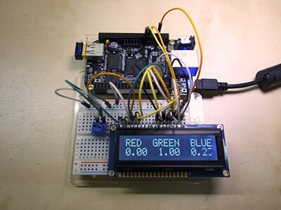
# Set LCD color to green
lcd.color = [0, 0, 100]
time.sleep(1)
# Set LCD color to purple
lcd.color = [50, 0, 50]
time.sleep(1)
lcd.clear()
# Print two line message right to left
lcd.text_direction = lcd.RIGHT_TO_LEFT
lcd.message = "Hello\nCircuitPython"
# Wait 5s
time.sleep(5)
# Return text direction to left to right
lcd.text_direction = lcd.LEFT_TO_RIGHT
# Display cursor
lcd.clear()
lcd.cursor = True
lcd.message = "Cursor! "
# Wait 5s
time.sleep(5)
# Display blinking cursor
lcd.clear()
lcd.blink = True
lcd.message = "Blinky Cursor!"
# Wait 5s
time.sleep(5)
lcd.blink = False
lcd.clear()
# Create message to scroll
scroll_msg = "<-- Scroll"
lcd.message = scroll_msg
# Scroll to the left
for i in range(len(scroll_msg)):
time.sleep(0.5)
lcd.move_left()
lcd.clear()
time.sleep(1)
lcd.message = "Going to sleep\nCya later!"
time.sleep(5)
# Turn off LCD backlights and clear text
lcd.color = [0, 0, 0]
lcd.clear()
Text editor powered by tinymce.
F.A.Q.
I have a monochrome display and some of the buttons don't work.
The monochrome display only responds to backlight colors with RED in them. Use "ON" and "OFF" instead. See the code snippet under "Using with Monochrome Displays."
What pins are used? What pins are available?
The shield uses only the SCL and SDA I2C pins, and 5V power and ground. You can use the I2C pins for other I2C sensors/devices as long as they do not share the same address. If you are using an Arduino UNO, Analog 4 and Analog 5 are shared with SCL/SDA so you can't use them. Likewise, Arduino Leonardo share SCL/SDA with Digital 2 & Digital 3 so those would not be available.
I'm trying to compile and I'm getting error messages like "No such file or directory" or "does not name a type".
If you're seeing error messages that look like any (or all) of the following, it means that the Arduino IDE is not finding the Adafruit libraries.
There are three possible causes for this:
Once you've made sure the folder has the right name and is in the right place, you have to close and reopen the Arduino IDE, so that it will recognize the new library.
if you're curious, you can learn more about libraries here:
http://learn.adafruit.com/arduino-tips-tricks-and-techniques/arduino-libraries
Does the shield do the button de-bounce logic internally, or do I need to do that in software when reading the buttons?
The Adafruit_RGBLCDShield library handles button debouncing for you, when you use the readButtons() function.
Is this compatible with my Arduino? There are two extra pins on the header that don't plug into anything.
The shield will work fine with older Arduino boards. Extra pins were added to the R3 version of the Uno and Mega. These are duplicates of other header pins and are not required for proper operation of the shield.
Does this work with the Raspberry Pi?
At this time, it does not! This shield is for Arduinos only!
I am using this detached from the Arduino and it doesn't seem to be getting any power.
Only the ground pin next to the VIN pin is used. You need to connect your ground wire to this pin.
Can I use this with 20x4 LCDs?
Technically, yes. The pinouts for 20x4 and 16x2 are identical. However, the screen is way bigger, and it covers the buttons up, so we don't suggest it.
Text editor powered by tinymce.
Downloads
Files
Schematic and Fab Print
Rev B
Rev A
Text editor powered by tinymce.