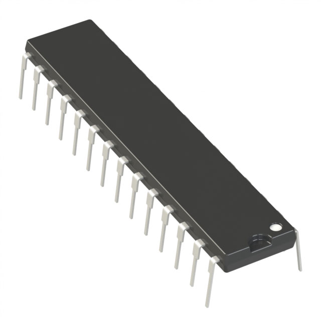
制造商零件编号 MCP23008-E/P
IC XPNDR 1.7MHZ I2C 18DIP
Microchip Technology
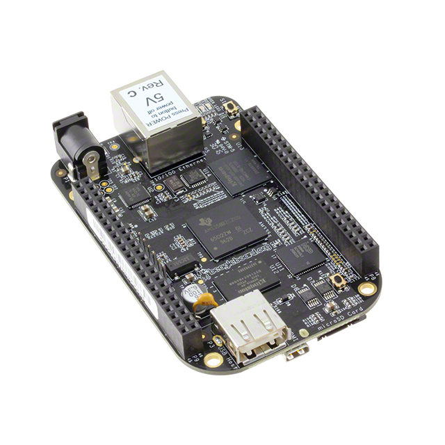
License: See Original Project BeagleBone Raspberry Pi SBC
Courtesy of Adafruit
Guide by Tony DiCola
Overview
Looking for a simple way to add a text display to your Raspberry Pi or BeagleBone Black project? Consider using a character LCD with the Python character LCD library! These classic displays can show a few lines of text, are inexpensive, and easily readable during the day or night with a bright backlight. You can follow this guide to learn how to connect a character LCD to a Raspberry Pi or BeagleBone Black and control the display from your own Python code!
Before you get started it will help to familiarize yourself with the character LCD guide. You will also want to make sure your Raspberry Pi is running the latest Raspbian operating system, and your BeagleBone Black is running the latest Debian or Debian-based distribution like Ubuntu.
If you haven't used a Raspberry Pi or BeagleBone Black, be sure to follow the Learn Raspberry Pi series or BeagleBone Black SSH guide to understand the basic usage of each board and how to connect to a command terminal.
When you're ready to get started, grab a character LCD, contrast adjustment potentiometer (included with Adafruit character LCDs), and a Raspberry Pi or BeagleBone Black. Continue to the next page to learn how to wire the display to your board.
Wiring
Follow the steps below to wire a character LCD to your development board. Be careful to connect each wire to the correct pins as there are quite a few wires necessary to use the character LCD.
Note: The wiring below is for an RGB backlight display. If you're using a monochrome backlight display you can use the wiring as-is and ignore the green and blue backlight wires. The red backlight wire will be used to control the monochrome display's backlight.
If you would like to permanently turn on the LCD backlight, connect the red, green, blue backlight wires to ground instead of to your development board.
Raspberry Pi
Wire your character LCD to the Raspberry Pi as follows:
BeagleBone Black
Wire your BeagleBone Black to the LCD as follows. If you aren't familiar with how to identify pins on the board, be sure to read the BeagleBone Black GPIO guide.
BeagleBone Black with PWM
The above wiring will use digital IO to control the colors of the backlight display. This means the backlight can only show 7 different colors (all the combinations of the 3 backlight LEDs). However because the BeagleBone Black supports PWM (pulse-width modulation) control of some hardware pins, it's possible to use PWM pins to control the backlight LEDs and display a range of almost all colors.
To use PWM control of the backlight LEDs, wire your BeagleBone Black to the LCD as follows. Note that this wiring is exactly the same as the non-PWM wiring, except the 3 backlight LED pins (red, green, blue) are moved to different pins.
Usage
Dependencies
Before installing the character LCD library you'll need to make sure a few dependencies are installed by following the steps below. Make sure your development board has access to the internet so the software can be downloaded.
Raspberry Pi
On the Raspberry Pi execute the following commands in a terminal/SSH session on the Pi:
sudo apt-get update
sudo apt-get install build-essential python-dev python-smbus python-pip git
sudo pip install RPi.GPIO
You can ignore any warnings about dependencies already being installed.
BeagleBone Black
On the BeagleBone Black execute the following commands in a terminal/SSH session on the device:
sudo apt-get update
sudo apt-get install build-essential python-dev python-smbus python-pip git
sudo pip install Adafruit_BBIO
You can ignore any warnings about dependencies already being installed.
Installation
Once the dependencies above have been installed you can install the character LCD module by executing the following commands on the device:
cd ~
git clone https://github.com/adafruit/Adafruit_Python_CharLCD.git
cd Adafruit_Python_CharLCD
sudo python setup.py install
These commands will clone the GitHub repository with the library source and then execute the setup.py script to install the library.
Usage
Once the library is installed you can find a few examples of its usage in the examples subdirectory. If you're using a monochrome backlight LCD (i.e. single color, like a white on blue LCD) the char_lcd.py script will demonstrate the basic usage.
If you're using a Raspberry Pi and have wired it according to this guide, you can immediately run the example. However if you're using a BeagleBone Black or changed the wiring, first open char_lcd.py in a text editor (like nano) and uncomment/comment the lines towards the top that set the LCD pins.
Note: If you're using a BeagleBone Black wired for hardware PWM of the backlight, skip down the page to the section on using hardware PWM.
To run the example execute:
cd examples
python char_lcd.py
You should see the LCD backlight turn on and messages printed to the display. For example below is what you will see with a 20x4 blue backlight LCD:
To demonstrate the usage of the library I'll walk through the source code of the char_lcd.py example below.
import math
import time

import Adafruit_CharLCD as LCD
The first part of the script are commands to import modules that will be used. In particular the Adafruit_CharLCD module is imported under the name LCD. Later in the script you can see how classes from the char LCD module are used to interact with the LCD.
# Raspberry Pi pin configuration:
lcd_rs        = 27  # Note this might need to be changed to 21 for older revision Pi's.
lcd_en        = 22
lcd_d4        = 25
lcd_d5        = 24
lcd_d6        = 23
lcd_d7        = 18
lcd_backlight = 4

# BeagleBone Black configuration:
# lcd_rs        = 'P8_8'
# lcd_en        = 'P8_10'
# lcd_d4        = 'P8_18'
# lcd_d5        = 'P8_16'
# lcd_d6        = 'P8_14'
# lcd_d7        = 'P8_12'
# lcd_backlight = 'P8_7'
The next part of the script configures which pins are connected to the LCD. You can see the Raspberry Pi configuration is uncommented by default, and below it the BeagleBone Black configuration is commented. You can use any digital GPIO pins in the configuration.
# Define LCD column and row size for 16x2 LCD.
lcd_columns = 16
lcd_rows    = 2

# Alternatively specify a 20x4 LCD.
# lcd_columns = 20
# lcd_rows    = 4
This section of the script configures the size of the LCD. By default the code assumes a 16 column, 2 row LCD however you can adjust the configuration to a 20x4 or other size display supported by the HD44780.
# Initialize the LCD using the pins above.
lcd = LCD.Adafruit_CharLCD(lcd_rs, lcd_en, lcd_d4, lcd_d5, lcd_d6, lcd_d7,
                           lcd_columns, lcd_rows, lcd_backlight)
Next an instance of the Adafruit_CharLCD class is created based on the configuration specified earlier in the script.
# Print a two line message
lcd.message('Hello\nworld!')

# Wait 5 seconds
time.sleep(5.0)

# Demo showing the cursor.
lcd.clear()
lcd.show_cursor(True)
lcd.message('Show cursor')

time.sleep(5.0)

# Demo showing the blinking cursor.
lcd.clear()
lcd.blink(True)
lcd.message('Blink cursor')

time.sleep(5.0)

# Stop blinking and showing cursor.
lcd.show_cursor(False)
lcd.blink(False)
The next lines demonstrate basic usage of the LCD display class. The message function can be used to write a string of text to the display (including support for line breaks). The clear function clears the display, and the show_cursor and blink functions specify if the cursor is shown and should blink.
Although not shown above, there are other functions you might find useful on the LCD class. To see details on all functions you can have Python print help text for the class by executing (ignore the >>> prompt, it's only shown for reference as the Python interpreter):
python
>>> import Adafruit_CharLCD as LCD
>>> help(LCD.Adafruit_CharLCD)
You should see a description of each function on the LCD class, including some functions not shown in the example:
Finally, the last portion of the char_lcd.py script:
# Demo scrolling message right/left.
lcd.clear()
message = 'Scroll'
lcd.message(message)
for i in range(lcd_columns-len(message)):
    time.sleep(0.5)
    lcd.move_right()
for i in range(lcd_columns-len(message)):
    time.sleep(0.5)
    lcd.move_left()

# Demo turning backlight off and on.
lcd.clear()
lcd.message('Flash backlight\nin 5 seconds...')
time.sleep(5.0)
# Turn backlight off.
lcd.set_backlight(0)
time.sleep(2.0)
# Change message.
lcd.clear()
lcd.message('Goodbye!')
# Turn backlight on.
lcd.set_backlight(1)
You can see how the move_right and move_left functions are used to scroll the display, and further down how the set_backlight function turns off and on the backlight.
That's all there is to using the Adafruit_CharLCD class!
RGB Character LCD
If you're using an RGB backlight LCD the char_lcd_rgb.py script will demonstrate the usage.
If you're using a Raspberry Pi and have wired it according to this guide, you can immediately run the script. However if you're using a BeagleBone Black or have changed the wiring, edit the script with a text editor and uncomment/change the lines at the top that define the LCD pins.
To execute the RGB backlight example run this command from inside the examples directory:
sudo python char_lcd_rgb.py
You should see the LCD turn on and display different backlight colors. For example:
If you open the file char_lcd_rgb.py in a text editor (such as nano) I'll describe the important differences between it and the previous char_lcd.py example below.
# Example Raspberry Pi configuration:
lcd_rs = 27  # Change this to pin 21 on older revision Raspberry Pi's
lcd_en = 22
lcd_d4 = 25
lcd_d5 = 24
lcd_d6 = 23
lcd_d7 = 18
lcd_red   = 4
lcd_green = 17
lcd_blue  = 7  # Pin 7 is CE1

# Example BeagleBone Black configuration:
# lcd_rs = 'P8_8'
# lcd_en = 'P8_10'
# lcd_d4 = 'P8_18'
# lcd_d5 = 'P8_16'
# lcd_d6 = 'P8_14'
# lcd_d7 = 'P8_12'
# lcd_red   = 'P8_7'
# lcd_green = 'P8_9'
# lcd_blue  = 'P8_11'
The first important difference is the configuration of LCD pins. Notice there are now explicit pins defined for the red, green, and blue backlight LEDs.
# Initialize the LCD using the pins
lcd = LCD.Adafruit_RGBCharLCD(lcd_rs, lcd_en, lcd_d4, lcd_d5, lcd_d6, lcd_d7,
                              lcd_columns, lcd_rows, lcd_red, lcd_green, lcd_blue)
The next line creates an instance of the Adafruit_RGBCharLCD class using the pin configuration defined earlier.
The Adafruit_RGBCharLCD class inherits from the Adafruit_CharLCD class so it has all the same functionality as demonstrated in the char_lcd.py example. In addition to the basic character LCD functionality the RGB character LCD class adds some functions to set the RGB color of the backlight.
# Show some basic colors.
lcd.set_color(1.0, 0.0, 0.0)
lcd.clear()
lcd.message('RED')
time.sleep(3.0)

lcd.set_color(0.0, 1.0, 0.0)
lcd.clear()
lcd.message('GREEN')
time.sleep(3.0)

lcd.set_color(0.0, 0.0, 1.0)
lcd.clear()
lcd.message('BLUE')
time.sleep(3.0)

lcd.set_color(1.0, 1.0, 0.0)
lcd.clear()
lcd.message('YELLOW')
time.sleep(3.0)

lcd.set_color(0.0, 1.0, 1.0)
lcd.clear()
lcd.message('CYAN')
time.sleep(3.0)

lcd.set_color(1.0, 0.0, 1.0)
lcd.clear()
lcd.message('MAGENTA')
time.sleep(3.0)

lcd.set_color(1.0, 1.0, 1.0)
lcd.clear()
lcd.message('WHITE')
time.sleep(3.0)
The code above demonstrates each basic color by calling the set_color function and passing in which red, green, and blue LEDs to enable. For example the first call to set_color(1.0, 0.0, 0.0) will turn on the red LED and turn off the green and blue LED so the backlight will have a red color.
Notice how later lines combine multiple LEDs to get different colors, like calling set_color(1.0, 0.0, 1.0) to combine red and blue LEDs for a magenta/violet color.
RGB Character LCD with PWM
If you're using a RGB character LCD you can use PWM (pulse-width modulation) for fine control of the backlight color. By turning the different backlight red, green, and blue LEDs on and off very quickly with PWM, it's possible to precisely control the color of the backlight.
Note that PWM control works best when there's hardware support for PWM on your development board. The BeagleBone Black has support for up to 8 hardware controlled PWM pins and works great with the RGB character LCDs. However, the Raspberry Pi only has one hardware PWM pin and can be a little more troublesome to use PWM.
The RPi.GPIO library which is used by the character LCD library supports a software implementation of PWM on the Raspberry Pi. This lets you PWM control the RGB backlight even though the Pi doesn't have 3 hardware PWM pins. In my testing software PWM worked reasonably well with the RGB character LCD backlight. You might notice slightly incorrect colors, but otherwise software PWM is worth a shot to finely adjust the backlight color on the Raspberry Pi.
The char_lcd_rgb_pwm.py file demonstrates usage of PWM backlight control. If you're using a Raspberry Pi and have it wired to the LCD as described in this guide, you can immediately run the script. However if you have a BeagleBone Black or have changed the wiring, edit the file char_lcd_rgb_pwm.py in a text editor and comment/uncomment the lines at the top which define the LCD pins.
If you're using the BeagleBone Black make sure you've followed the wiring for hardware PWM. Specifically, the red, green, and blue backlight pins need to be connected to the P9_16, P9_14, and P8_13 pins respectively.
To run the example, make sure you're in the examples folder and run:
sudo python char_lcd_rgb_pwm.py
You should see the backlight turned on to different colors for a short period of time, and then a continuous gradient of colors displayed with a message showing the red, green, and blue color displayed on the LCD. For example:
You can press Ctrl-C to top the script.
The code for PWM control is very similar to non-PWM control from char_lcd_rgb.py, however there are a few important differences. The first difference is how the Adafruit_RGBCharLCD class is intialized. Notice the enable_pwm=True flag is passed to the constructor/init function:
# Initialize the LCD using the pins
lcd = LCD.Adafruit_RGBCharLCD(lcd_rs, lcd_en, lcd_d4, lcd_d5, lcd_d6, lcd_d7,
                              lcd_columns, lcd_rows, lcd_red, lcd_green, lcd_blue,
                              enable_pwm=True)
MCP230xx IO Expander
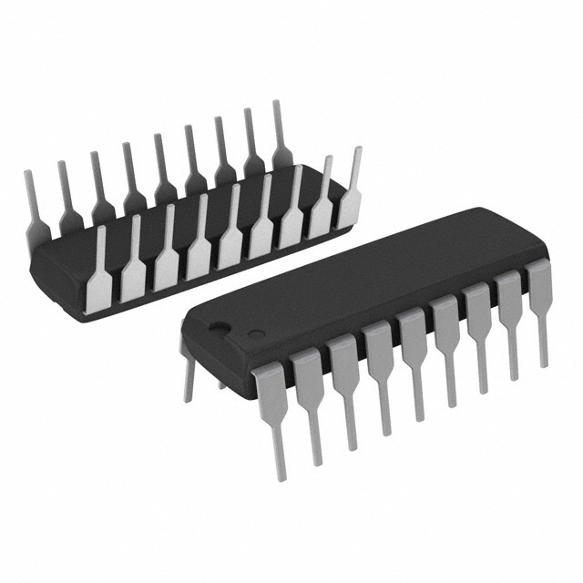
One problem with using a character LCD is that you give up a lot of GPIO pins to talk to the LCD. Four pins are used to send data, two pins are used for write and clock signals, and another pin or three are used for the backlight for a total of ~6-9 total pins! On a platform like the Raspberry Pi model A/B with only a dozen or so GPIO pins you can quickly run out of pins for other parts of your project. However with chips like the MCP23008 or MCP23017 you can easily add extra GPIO pins to your development board through an I2C interface!
If you aren't familiar with the MCP230xx series of chips, there's a great guide that describes their usage with a Raspberry Pi. Note that you don't need to install the library or code from the guide, it's only provided for reference.
Wiring
To use an MCP230xx chip with a character LCD you will need to wire the MCP chip to your board's I2C pins, and then wire the LCD to the MCP chip. Below are examples of wiring an MCP23017 to the Raspberry Pi or BeagleBone Black.
If you'd like to use an MCP23008 instead of the MCP23017 the wiring is similar, however consult the MCP23008 datasheet to see which pins are for power, ground, I2C, and GPIO.
Raspberry Pi
Wire your MCP23017 and LCD as follows:
Make sure you've enabled I2C on the Raspberry Pi if you haven't done so already.
BeagleBone Black
Wire your MCP23017 and LCD as follows:
Note that the BeagleBone Black has two I2C interfaces and this wiring will use the/dev/i2c-1 interface. Make sure there aren't any device tree overlays loaded which use these I2C pins for other purposes. The default BeagleBone Black device tree configuration with no overlays loaded will expose the necessary I2C interface for the wiring above.
Usage
The char_lcd_mcp.py file in the library's examples folder demonstrates the usage of a character LCD (non-RGB version) with an MCP23017 IO extender. Run the script by executing this command inside the examples directory:
sudo python char_lcd_mcp.py
You should see a simple demo of the LCD displaying text, cursors, and scrolling just like the char_lcd.py demo described on the previous page.
If you open char_lcd_mcp.py in a text editor you can see how to use the character LCD library with the MCP chip. Below is an overview of the file:
import math
import time

import Adafruit_CharLCD as LCD
import Adafruit_GPIO.MCP230xx as MCP
First the required modules are imported. Notice the addition of the Adafruit_GPIO.MCP230xx module (imported under the name MCP). This MCP230xx class will be used to talk to the MCP chip and interface with the LCD.
# Define MCP pins connected to the LCD.
lcd_rs        = 0
lcd_en        = 1
lcd_d4        = 2
lcd_d5        = 3
lcd_d6        = 4
lcd_d7        = 5
lcd_backlight = 6
# Optionally if the backlight is not controllable then set:
# lcd_backlight = None

# Define LCD column and row size for 16x2 LCD.
lcd_columns = 16
lcd_rows    = 2

# Alternatively specify a 20x4 LCD.
# lcd_columns = 20
# lcd_rows    = 4
Next the LCD pins are defined in the script. Note that these pin numbers are the MCP chip GPIO pin numbers, and NOT Raspberry Pi/BeagleBone Black pin numbers!
# Initialize MCP23017 device using its default 0x20 I2C address.
gpio = MCP.MCP23017()

# Alternatively you can initialize the MCP device on another I2C address or bus.
# gpio = MCP.MCP23017(0x24, busnum=1)
Next an instance of the MCP23017 class is created. By default this class will use the I2C address 0x20 (default for MCP chips) and appropriate I2C bus for the running development board. However if you need to override the address or bus number you can see in the commented line how these are passed as parameters.
Also note if you're using an MCP23008 chip you can instead create an instance of the MCP23008 class. This class is exactly the same as the MCP23017 class, but only supports 8 GPIO pins.
# Initialize the LCD using the pins
lcd = LCD.Adafruit_CharLCD(lcd_rs, lcd_en, lcd_d4, lcd_d5, lcd_d6, lcd_d7,
                           lcd_columns, lcd_rows, lcd_backlight, gpio=gpio)
Now the Adafruit_CharLCD class instance is created. The big difference with this line and previous examples is that the MCP23017 class (created with the name 'gpio') is passed in as the gpio parameter. By passing in an explicit gpio parameter, the char LCD class will use that GPIO class for talking to the LCD instead of the default development board GPIO pins.
The rest of the example code is exactly the same as the non-MCP character LCD example. You only need to change the setup and initialization of the character LCD class to use the MCP IO extender with an LCD!
Note you can also use an RGB character LCD with an MCP IO extender, however the MCP IO extender does NOT support PWM control of the backlight!
Raspberry Pi Char LCD Plate
The character LCD plate is a great way to add a simple character LCD and buttons to your Raspberry Pi project. Because the character LCD plate is based on the MCP23017 IO expander, the character LCD library easily supports the character LCD plate!
If you aren't familiar with the character LCD plate, make sure to first read the guide on its usage.
To use this character LCD library with the plate, make sure the library is installed by following the steps on the usage page. Then connect the LCD plate to your Raspberry Pi and execute the char_lcd_plate.py script in the library's examples folder:
sudo python char_lcd_plate.py
Note that the example assumes an RGB character LCD is attached to the plate, however it will still run with a monochrome LCD (you just might see the backlight turn on and off in different ways as colors as displayed).
When you run the example you should see the backlight run through different colors, and then the display will tell you to press buttons. If you press different buttons on the LCD plate you should see the button name and a different color displayed. Try pressing buttons to see how the script reacts!
Examine the code for the char_lcd_plate.py script to see how to use the character LCD plate code. The usage of the LCD plate is very similar to RGB or monochrome LCD usage, with a few key differences.
The first difference is that you create and instance of the Adafruit_CharLCDPlate class. You don't need to pass any parameters in to this class' constructor/init function because it is preconfigured for the LCD plate.
# Initialize the LCD using the pins
lcd = LCD.Adafruit_CharLCDPlate()
The second difference is that the Adafruit_CharLCDPlate adds a function to test if a button is pressed. Notice how the is_pressed function is called for each button, and if it returns True then the button press is detected.
For example to check if the select button is pressed you can call is_presssed(LCD.SELECT), or to check if the right button is pressed you can call is_pressed(LCD.RIGHT).
# Make list of button value, text, and backlight color.
buttons = ( (LCD.SELECT, 'Select', (1,1,1)),
            (LCD.LEFT,   'Left'  , (1,0,0)),
            (LCD.UP,     'Up'    , (0,0,1)),
            (LCD.DOWN,   'Down'  , (0,1,0)),
            (LCD.RIGHT,  'Right' , (1,0,1)) )

print 'Press Ctrl-C to quit.'
while True:
    # Loop through each button and check if it is pressed.
    for button in buttons:
    	if lcd.is_pressed(button[0]):
    		# Button is pressed, change the message and backlight.
    		lcd.clear()
    		lcd.message(button[1])
    		lcd.set_color(button[2][0], button[2][1], button[2][2])
One final thing to note, just like using an MCP230xx IO extender the character LCD plate does not support PWM control of the backlight LEDs!
That's all there is to using the character LCD plate with the character LCD Python library!