CAD (Computer Aided Design) 101
2024-09-23 | By Judith Settle
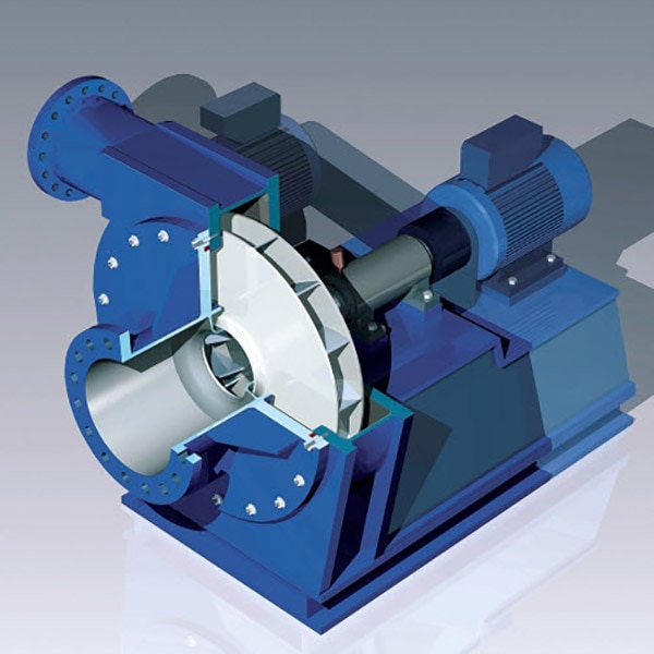
CAD (Computer Aided Design) combines Engineering with Art. It is the blueprint for any product you may think of before having to physically make it. CAD has also been used to improve already existing products and can be used in the patent process. This ensures that your ideas are protected even before your funding is secured or even if your product hasn’t been made. The basics of a CAD drawing include dimensions, materials, and tolerances. When using a CAD software, you are able to break a system into smaller subsystems that eventually come together to form the final product. In CAD, these are called assemblies and subassemblies.

A CAD project usually starts with a sketch. The sketches can include many different components, and where symmetry is involved, it even allows you to only have to design the part of the project that can be repeated. For example, you can draw a quarter of a circle and flip it about a center line both vertically and horizontally and keep symmetry throughout. This seems simple at first, but as your design becomes more intricate, you will notice using these small tricks later add up and save lots of time. Another parameter you can set is dimension. In my previous circle example, you can add width and make it into a ring. As you’re adding more details, you will notice the software will tell you when something is fully defined. This means that the appropriate dimensions have been specified enough so someone can print to a 3D printer, for example. Tolerances can also help ensure that the drawing is made so the product is effective. Tolerances tell the person creating the product what the size range can be. It will state more or less how precise you need to be when making the part and whether a certain material can and should be used to be more efficient. Once sketches have been made, you can start forming assemblies.
Assemblies can be formed through a collection of individual sketches, which independently were turned into parts. You start to join the parts together through something called mates. Think of mates as ways to adhere things in real life. This can be nails, screws, adhesives, etc. You will notice if a design is not mated fully that the parts can be clicked and dragged from where they aren’t connected. This helps you plan where the product may need to be sealed if and when it is made.

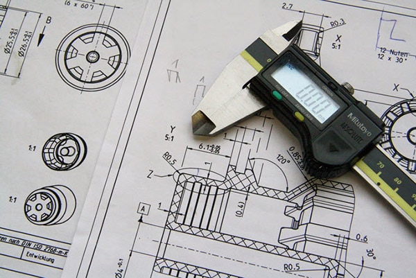
These assemblies then can be presented as items called drawings. The drawings can show different views or perspectives that help understand and produce the part. Some can be made for you, such as front, top, and left orientations. You can also include your dimensions on this drawing as well as a Bill of Materials (BOM). The Bill of Materials breaks down the parts and how many there are, while providing a description, and a part number if you want. Drawings include a title block that can state the title, which revision number this is, the date, and other factors you deem important.
As you start to familiarize yourself with a CAD software, it is important to note shortcuts you can use when designing. As you learn more shortcuts, you save time by having to avoid searching the menus. CAD is used in many Engineering fields and when making almost every product you can think of. These are great ways to effectively relay information to teams working on a product. You can also divvy up the work based on which assemblies and parts go to which teams. Since CAD is used so widely in the industry, I recommend that as you are learning, you find certifications to add to your resume. These skills will help you stand out because they show that you are thinking like an engineer and being mindful of how tolerances, materials, and dimensions can affect your product.


 中国
中国