制造商零件编号 A000073
ARDUINO UNO SMD R3 ATMEGA328
Arduino
I'm working on a project, and I want to control a whole bunch of LEDs, but I don't have enough GPIO pins on my microcontroller. If you’ve been tinkering with electronics for any amount of time, you’ve probably run into this situation before. Maybe it wasn’t LEDs, but some other output like relays. Or maybe you were trying to read a ton of button inputs and you were short on GPIO pins. I'm going to show you how to solve this problem and potentially save your project by using a technique called multiplexing.

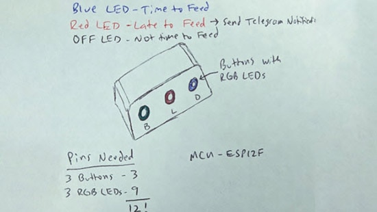
The project I'm working on is actually for a friend of mine. He recently got a new puppy and he's having a hard time remembering whether or not he has fed the puppy throughout the day. So, he designed a really cool project that will remind him to feed his dog using some RGB LEDs and buttons. His design has three RGB LEDs and three buttons that he needs to control with a microcontroller. If you're familiar with RGB LEDs, you know that they have three LEDs built into one and they usually share a common anode or a common cathode. My friend got stuck at this point in his design process because after connecting the buttons, he didn't have enough GPIO pins left over to control that many LEDs. This is where multiplexing comes in handy. To put it simply, instead of assigning each LED or button its own dedicated GPIO pin, I can reduce the number of GPIO pins needed by having these devices share pins. Let me show you what I'm talking about.
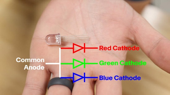
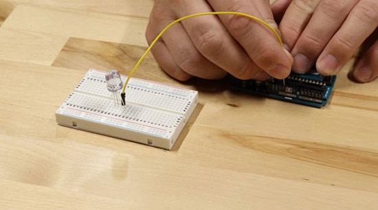
Let's assume that I want to assign a dedicated GPIO pin for each RGB in the feed-the-dog reminder circuit. I would need nine GPIO pins just to control all three of the RGB LEDs! But what would happen if I grouped all of the red LEDs together, all of the green LEDs together, and all of the blue LEDs together? I can start by connecting just one RGB LED to my microcontroller. The common anode gets connected to 5V, while the red, green, and blue cathodes get connected to three GPIO pins through current-limiting resistors. I can turn on each RGB by pulling the corresponding GPIO pin low. To turn off the LED, I pull the same GPIO pin high. Now let's add a second RGB LED. The red, green, and blue cathodes get connected to the same GPIO pins through current limiting resistors, just like before. The two red cathodes share a pin, the two green cathodes share a pin, and the two blue cathodes share a pin. But what do I do with the common anode? Do I connect it to 5V like I did the other one? Well, let's try that and see what happens.
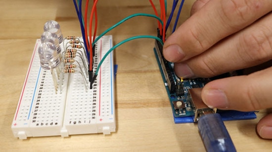
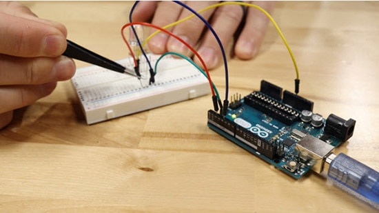
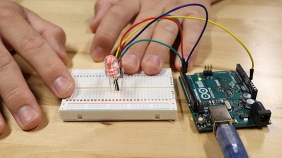
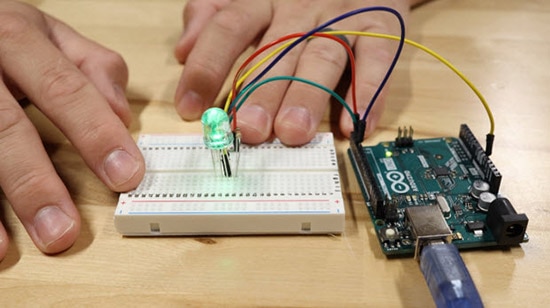
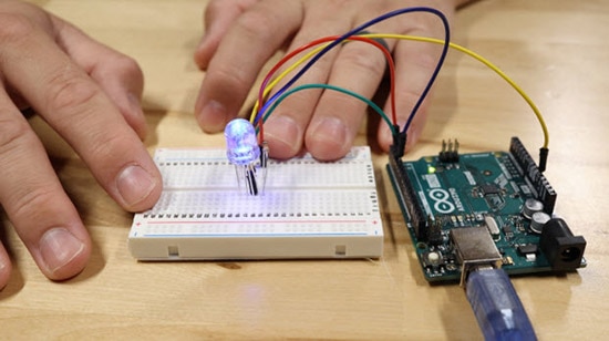
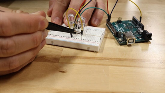
So now I have both common anodes connected to 5V, but when I try to turn on a single red LED, they both come on. I'm not able to turn on a single red LED, the whole color group turns on. To fix this problem, I need to remove both anodes from 5V and assign them their own dedicated GPIO pin. This way I can separate the color groups into individual LEDs. If I want to add a third LED, I just follow the same pattern. I can keep adding more and more RGB LEDs in the same way and still be able to control them individually.
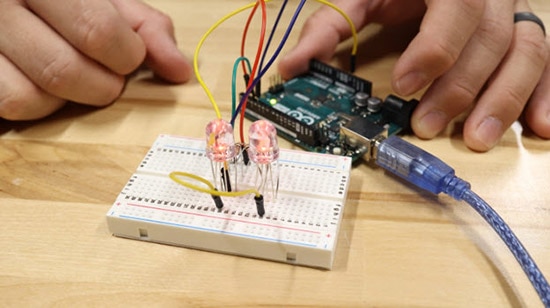
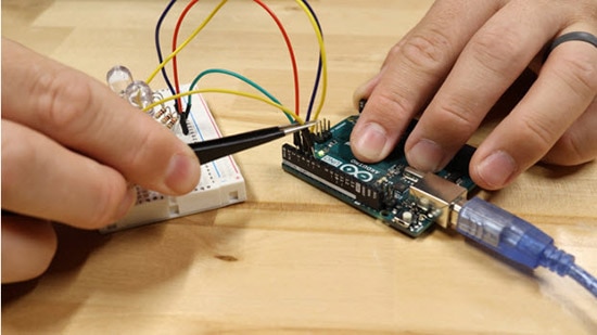
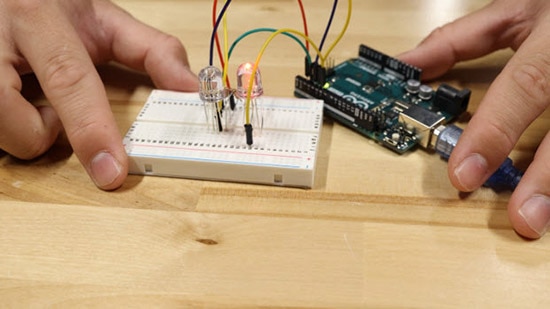
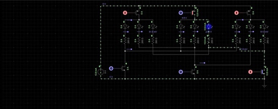
Here's what the circuit diagram looks like. The three GPIO pins on the bottom are for the three different colors red, green, and blue. While the GPIO pins on top are for the anodes, one for each LED. You'll notice that each individual LED has its own current limiting resistor. I don't want to share current limiting resistors among different LEDs. I can turn on and off different pins to individually control all nine LEDs. For example, if I want to individually turn on the middle blue LED, first I would need to set the GPIO pin controlling the middle anode to high. Then I would need to set the GPIO pin controlling the blue LED's cathodes low. In this example, I'm using very low current LEDs so that the GPIO pins themselves can source and sync all of the current. If I was going to use higher current LEDs or some other component that draws more current, I would obviously need to include a MOSFET or some other transistor in the circuit to do all of the heavy lifting. If my LEDs used a common cathode instead of a common anode this is what the circuit would look like. The function is very similar, it's just using the common cathode instead of the common anode.



So, we've seen how multiplexing can be used to reduce GPIO pins for outputs. But what about inputs? To help explain that I'm going to use a matrix keypad. I have a numeric keypad here, which is often found on point-of-sale machines where you type in your PIN. This one has 16 individual buttons. If I were going to read these buttons individually, it would require 16 GPIO pins. But again, we can use multiplexing to reduce that number. Multiplexing is so common that these keypads generally come pre-wired with multiplexing in mind. So, to read all of these buttons instead of requiring 16 GPIO pins, it only requires eight. Generally speaking, I’ll need one GPIO pin for every column of a numeric keypad and one GPIO pin for every row of a keypad.

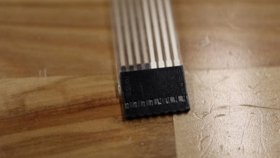
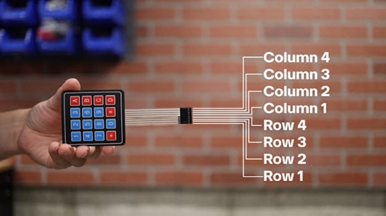
I want to get a better idea of what the internal circuit diagram looks like on one of these keypad matrices. To do that I'm going to start by describing what one row looks like. There is a GPIO pin that connects one terminal on all four switches. This single GPIO pin that connects all four switches will be an output. It will be driven at a logic high or a logic low. Then there are four more pins that connect to the other terminal of each of the switches. These will be inputs and be read by the microcontroller. For this example, I'm going to set the microcontroller to have an internal pulldown resistor on all four of these GPIO pins. This way I can set the output GPIO pin to a logic high and then pull each of the four switches to read their logic state. If any of the four pins read a logic high, I know that corresponding button has been pressed. If my microcontroller has enough interrupt pins, I would use those instead of a polling method. That explains how I can read four buttons, but how do we get to 16? I can add a second row of four switches and set it up similarly to the first row. The second row also has one GPIO pin that connects all four switches. This one is also set as an output on the microcontroller. Then I will connect the other side of the four switches to the same for GPIO pins as I did on the first row. You can see that I'm starting to create a matrix here. Each row has its own GPIO pin that is an output, and each column has its own pin that is an input. I can continue to add rows of switches until I get to 16 switches that are all connected in a matrix.


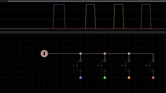
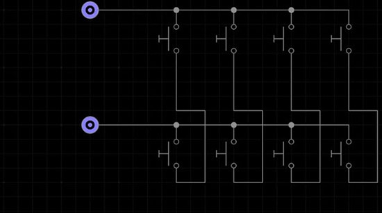
We can't set all of the open outputs to a logic high simultaneously. We have to get a little creative here with how we read these individual button presses. A common approach is going one row at a time, writing that GPIO output high and then reading the column inputs for all four switches. When I’m done reading the four GPIO pins for button presses I can write that output low and then I cycle down to the next row and start again. I set the output high and then read all four inputs for button presses and then write it low. I keep cycling down each row until I’ve finished, then I can start again at the top. With a little bit of additional code, I can prevent a single button press from being read as multiple button presses. By using this sort of sequence, I can read matrix keypads with quite a bit of precision.

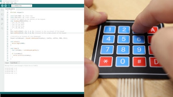
These two examples of LEDs and matrix keypads are really the most basic form of multiplexing. This topic is way more complex and goes a lot deeper. It's important to note that there are external ICs that are designed for multiplexing. You can use these external ICs in conjunction with your microcontroller to carry out much larger scale multiplexing tasks. Then there's also the topic of direct port manipulation within your microcontroller. If you're stuck with just a few GPIO pins, you can accomplish a variety of input and output tasks with just a little bit of code using direct port manipulation. This Arduino page explains the basic concept of direct port manipulation, and this DigiKey blog post explores this topic further and provides a really cool and practical example.
If multiplexing is a new concept for you, I recommend spending some time playing around with it and experimenting with the concepts that I talked about in this post.