How to Read and Use Encoders
2024-02-06 | By Zach Hipps
When working on projects, sometimes it's really useful to be able to track the rotation of an object. Whether that's the shaft of a spinning motor, or a knob that you turn to select an item on a user interface. In this post, I'll talk about how encoders work, and how to read them with a microcontroller. I'll even go over a couple of mistakes that I've made that you should avoid. Encoders come in two different varieties. There's the electromechanical kind that have physical switches that open and close inside them. Then there are the contactless kind that usually use magnetic fields or light to detect the rotating shaft.
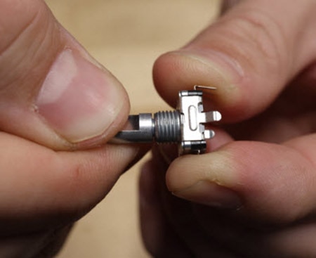
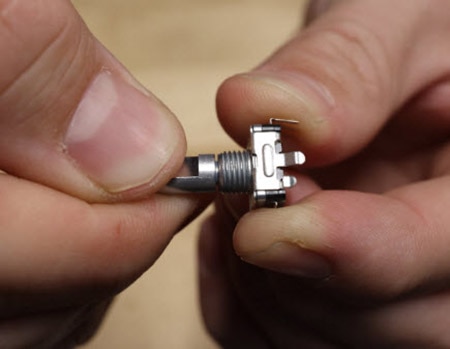
To start out, I'm going to talk about electromechanical encoders. If you’ve ever used a rotary encoder in a project, you are familiar with electromechanical encoders. These components have a little shaft that rotates, and as you spin it there are little detents in there that let the shaft fall into place. This provides physical feedback to let you know you're turning the knob. Rotary encoders are different from Potentiometers in a number of ways. First, there are no end limits. You can spin rotary encoders as many times as you want without ever running into an end stop. The other big difference is that potentiometers will vary the resistance on their output, whereas a rotary encoder produces square pulses that can be read by a microcontroller or other digital logic components. By keeping track of the number of pulses coming out of the rotary encoder, you can determine how far you've turned the shaft.
To show you what I'm talking about, I’ve drawn a little diagram. In the center, there’s a little shaft that is spinning clockwise, and I've placed a limit switch near that spinning shaft. If I add a little nub (that may or may not be the right technical term) sticking out of that spinning shaft. As it rotates, the nub comes into contact and closes the switch. I can read that pulse with a microcontroller and determine that the shaft has rotated to this exact position. The other cool thing that can be done with encoders is determining how fast a shaft is spinning. If I measure the time between pulses, I can calculate how fast that shaft is spinning.
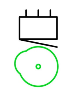
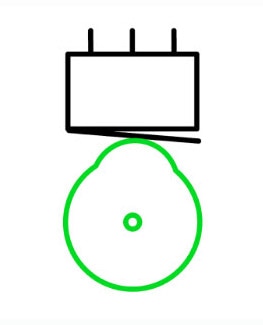
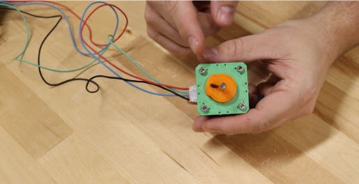
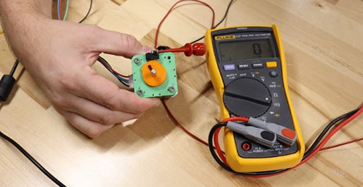
I'll demonstrate this concept a little bit more clearly using a stepper motor. The stepper motor is slowly spinning around, and I’ll attach a little disc that I 3D printed to help visualize what I'm talking about. If you look closely, you can see that this disc is not a perfect circle. It has a little nub sticking out where I have the black Sharpie mark. Now I'll attach a little limit switch which will come into contact with that nub as the shaft spins around. I connect my multimeter to the limit switch and put it in continuity mode. Then I'll turn on the motor, and as the shaft spins around and comes in contact and closes the switch, I can hear the multimeter beep. This is working great, but what if I want more resolution? Right now, I only have one nub that comes in contact with the switch, so it gives me one pulse per revolution of the shaft. If I wanted to get more resolution out of this crude encoder, I could add more nubs which would increase the number of pulses per revolution. Each time one of those nubs comes in contact with the limit switch, it generates a pulse.
To read the switch with a microcontroller I need to add some more to my diagram. I need to connect the normally closed terminal of the switch to ground, and the normally open terminal to 5V using a pull-up resistor. The common terminal is connected to a GPIO pin on my microcontroller. As the shaft spins and the switch closes, the GPIO pin will read a logic HIGH signal. The resolution of the encoder is measured by how many pulses per revolution it generates. I’ll represent the opening and closing of the switch, using a square wave diagram. Obviously, this is a very crude representation of an encoder. Real encoders have much higher resolutions. Often, you'll get hundreds of pulses per revolution.
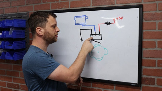

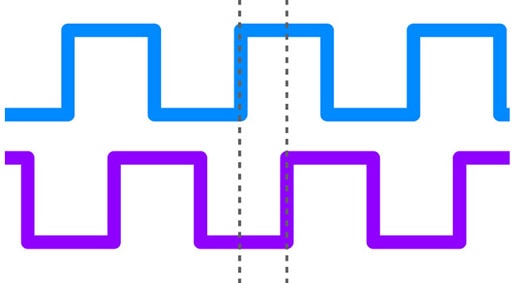
With this design, I can keep track of how much the shaft has turned, and I can also calculate how fast it's turning. But the big thing that I'm missing here is being able to tell whether the shaft is spinning clockwise or counterclockwise. As the high points are coming in contact with the switch, there's no way to tell whether the shaft is spinning clockwise or counterclockwise. For that, I'll need a second switch. Just like before I need to tie the normally closed terminal to ground, and I tie the normally open up to 5V using a pull-up resistor. The common terminal is then connected to a second GPIO pin on my microcontroller. Let's call the first switch “switch A” and use the color blue to draw a square wave diagram. The second switch is “switch B”, and I’ll use the color purple in my diagram. At the beginning of one revolution, both switches start open. That means both GPIO pins for A and B will read a logic LOW.
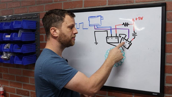
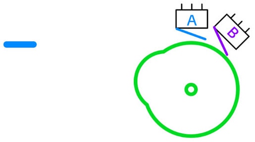
As the shaft rotates, switch A closes, and GPIO A reads a logic HIGH. At this point, switch B is still open, so GPIO B still reads a logic LOW. The shaft continues to rotate, eventually closing switch B as well. Now both GPIO pins A and B read logic HIGH. As the shaft continues to rotate, switch A opens first, which will make GPIO A read a logic LOW. Notice that switch B is still closed, so it's reading a logic HIGH. Finally, the shaft continues to rotate, causing switch B to open which results in both GPIO pins reading a logic LOW. This pattern starts over as the shaft rotates back to where it started.
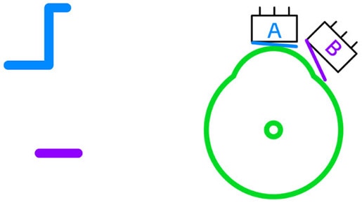
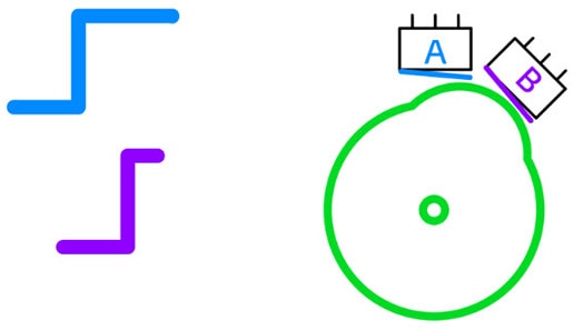
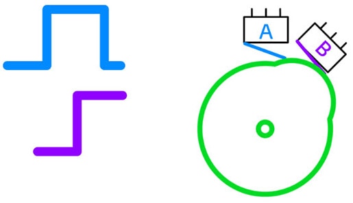
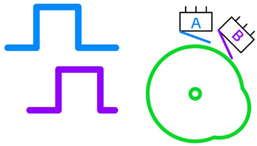
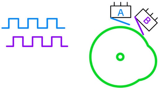
As you look closely at these square waves, you'll notice something really important. They are not in sync. The rising edges of each signal do not align but are offset by 90 degrees. Another way to describe this is saying that signal B is trailing behind signal A, and is 90 degrees out of phase. I can tabulate the states of each signal in a state table.
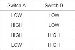
This pattern has a name, it's called quadrature encoding. The reason it's called a quadrature output is because there are four different possibilities that the outputs could be in.
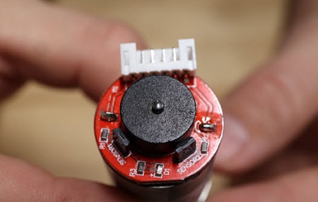
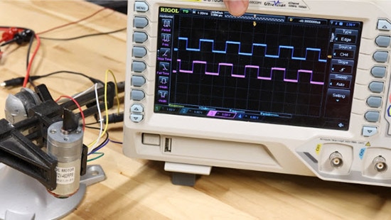
I should point out that, yes, it's possible to build an encoder like this using electromechanical switches, but this is not a good idea. The main reason is that electromechanical switches experience a lot of bouncing. Bouncing is when the contact inside of an electromechanical switch makes and breaks contact many times before it settles into a steady state. Each of those quick little bounces will be read as an encoder pulse. And if you're trying to keep track of your position, that could get really messy and difficult. Most encoders don't use electromechanical switches. Instead, they use contactless sensing, such as hall effect sensors or optical sensors. Here's an example of a DC motor that has an encoder on the back. Instead of using electromechanical switches, it has two hall effect sensors, and the disc that spins around is actually a magnet with north and south poles. The hall effect sensors read the change in polarity of the magnetic field.
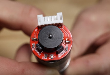
Let me connect this motor to a power supply and the oscilloscope to show you the signals. By reading both Signals A and B, not only can I read the position and speed of the shaft, I can also determine whether it is spinning clockwise or counterclockwise. As you can see, the motor is spinning clockwise. If I look at the waveform, I can see that the rising edge of switch A is leading the rising edge of switch B.
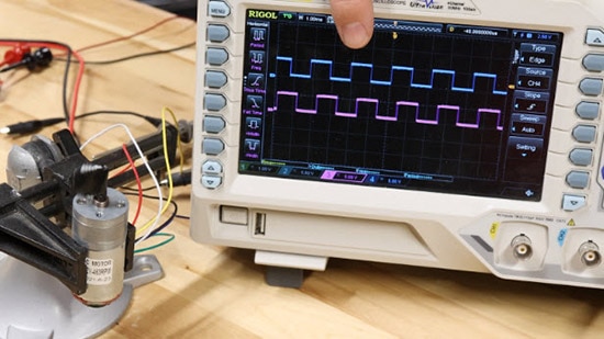
Now, if I swap the polarity of the power supply, the motor spins counterclockwise. Now when I look at the waveform, I can see that signal A is trailing signal B. This tells me that the motor is spinning counterclockwise.
I wrote a quick little Arduino sketch to show you a simple way to keep track of the position of a motor shaft. First, I used #define macros to define the two pins connected to the encoder output. One of these pins needs to be a hardware interrupt pin, and on the Arduino Nano that I’m using, I chose pin 2 for ENCODER_A. The other pin can be a general use pin, so I chose pin 4 for ENCODER_B.
#define ENCODER_A 2
#define ENCODER_B 4
void setup() {


}
void loop() {


}
In the setup() function, I begin the serial output which will be used for printing the motor position to the screen. I also need to attach the hardware interrupt to ENCODER_A. The interrupt service routine will be a function called updateMotorPosition, and I want to trigger this interrupt anytime there is a change (rising or falling edges) of ENCODER_A.
#define ENCODER_A 2
#define ENCODER_B 4
void setup() {
  Serial.begin(115200);
  attachInterrupt(digitalPinToInterrupt(ENCODER_A), updateMotorPosition, CHANGE);
}
void loop() {


}
Next, I need to write the function I just referenced so I created a new function with global scope called updateMotorPosition() and the function doesn’t return anything. Within this interrupt service routine, I need to compare the state of ENCODER_B with ENCODER_A. If they are different, a variable named motorPosition is increased, otherwise, the variable is decreased.
#define ENCODER_A 2
#define ENCODER_B 4
void updateMotorPosition(){
  if(digitalRead(ENCODER_B) != digitalRead(ENCODER_A)){
    motorPosition++;
  }
  else{
    motorPosition--;
  }
}
void setup() {
  Serial.begin(115200);
  attachInterrupt(digitalPinToInterrupt(ENCODER_A), updateMotorPosition, CHANGE);
}
void loop() {


}
Next, I need to create the motorPosition variable I just referenced and initialize it to zero, so I put that below my #define macros to give it a global scope. I need to make motorPosition a long type because it could potentially store very large values that could be positive or negative. I also make the variable volatile because it will be updated inside an interrupt service routine. Finally, I add a print statement in my loop() function that will continuously print out the motorPosition variable.
#define ENCODER_A 2
#define ENCODER_B 4


volatile long motorPosition = 0;


void updateMotorPosition(){
  if(digitalRead(ENCODER_B) != digitalRead(ENCODER_A)){
    motorPosition++;
  }
  else{
    motorPosition--;
  }
}


void setup() {
  Serial.begin(115200);
  attachInterrupt(digitalPinToInterrupt(ENCODER_A), updateMotorPosition, CHANGE);
}


void loop() {
  Serial.println(motorPosition);
}
To test this out, I can just spin the motor shaft by hand and watch the motorPosition variable change. And if I spin it the other way, I can see that the value comes back down.
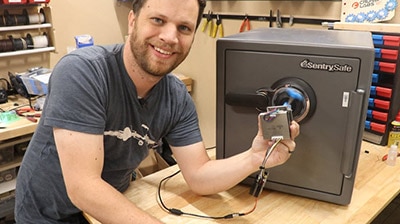
Earlier this year on the Byte Sized Engineering channel, I made a safe cracking robot and I used a stepper motor with an encoder to spin the safe dial. However, I made a really big mistake that cost me several weeks of frustration and troubleshooting, and the problem was how I implemented this very simple code above. Do you remember when I wrote the attach interrupt function and I set the mode to change? When I originally wrote that part, I set the mode to RISING. This just keeps track of the rising edges which I didn’t think would be a problem. Now that I know, this obviously creates a huge problem! It actually worked fine, as long as the motor was going in the same direction. But as soon as the motor changed direction back and forth, my motor position variable would drift over time. If you want to test this out, copy the code above but change the mode to RISING instead of CHANGE. As you spin the motor shaft back and forth, then return back to the starting point, it will not be zero as it should be.
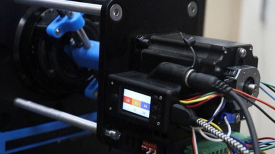
I couldn’t figure out why it was doing this, and I looked for problems everywhere including EMI noise on the encoder signals! If I had just put a little more thought into how I was counting pulses with direction changes, I would have realized my error sooner and saved myself a lot of frustration. So, I'm giving you this cautionary tale because I spent weeks banging my head against the wall trying to troubleshoot and I don’t want you to do the same thing as me! It was one of those expensive mistakes that I will always remember from now on.


