制造商零件编号 AFX00002
OPTA WIFI
Arduino
Similar to CAN, Modbus is an older yet widely used industrial communication protocol allowing data exchange between devices in a network. Read on to learn more about the protocol, its functionality, and how you can apply Modbus to your day-to-day projects.

Modbus is a serial communication protocol that primarily focuses on describing the message format, encoding, and addressing on a high level without dictating the underlying implementation on the physical layer. Each network comprises precisely one Modbus client and can accommodate anywhere from one to 247 Modbus servers. Each device on the bus has a unique address.
In Modbus RTU (Remote Terminal Unit), the client is the only device capable of actively requesting data on the network. Conversely, the servers can supply data via their internal registers when instructed by the server. Each server has a unique address in the network, and the client uses the server’s internal register addresses to retrieve data from a device.
Modbus is commonly used to transmit signals from instrumentation and control devices to a centralized controller. One example of this configuration could involve a system consisting of sensors measuring the temperature and vibrations of an electric motor in a factory crane. The collected data is then submitted to a computer for anomaly detection and to trigger safety measures when necessary. For such purposes, several versions of the Modbus standard exist to support common physical communication standards, such as RS-232, RS-485, and Ethernet.
The server devices store information and the client can either request register values or write values to registers. However, as Modbus is an older standard originally intended for use with industrial PLCs (Programmable Logic Controllers), the data tables defined by the protocol reflect this original design decision.
The binary coil object type represents discrete outputs and is typically used for controlling devices. Discrete inputs are the counterpart to the coils. These binary variables represent the state of binary inputs. Input registers are 16-bit read-only registers that hold analog data such as temperature readings or other sensor values. Furthermore, holding registers are 16-bit registers that the client can read from and write to, used for transmitting general data.
Finally, function codes enable the server to know what operation a client wants to perform. In Modbus RTU, function code 01 represents a read from multiple coils operation, 05 corresponds to writing a value to a single coil, 02 initiates a read from a discrete input, 04 lets the client read an input register, and function codes 03 and 06 let a client read and write holding register values.
Each request frame in Modbus RTU begins with 28 bits of silence to begin the transmission. Next, the server sends the eight-bit address of the client it wants to communicate with, followed by the eight-bit function code. Following is the data field, whose field length, contents, and meaning depend on the function code. The frame concludes with a 16-bit CRC error-correcting code followed by the end condition, which consists of 28 bits of silence on the data line.
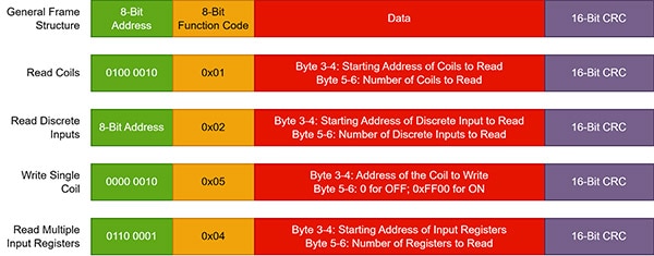
While all frames adhere to the same overall structure, the data field varies widely depending on the specific operation being performed and the quantity of coils or registers involved to read or write. The following image shows a few examples of requests in Modbus RTU:
 This image shows the general composition of request frames in Modbus RTU.
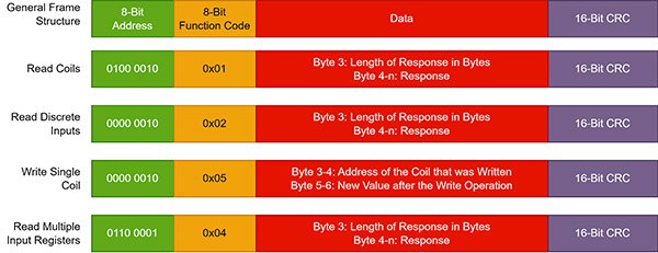
Across the requests, the data field typically follows the same structure, where the first two bytes define the starting address and the next two contain either a value to write or the number of registers/coils to read. The following images show examples of responses to these requests:
 This image shows the general composition of some example responses in Modbus RTU.
Note how the address and function code remain equal in the request and matching response. Read-request responses commonly adhere to a similar structure as well, where the first data byte denotes the number of bytes in the response, and the subsequent bytes contain the requested values. However, when writing a value the first two bytes contain the address of the modified coil, and the last two bytes in the data block contain the newly written value that must match the one found in the request.
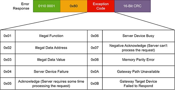
Aside from the normal response, the server can also reply with an error frame. In the normal frame, the response always repeats the function code in the request. In an error frame, the server replies with a function code of 0x80, and the response only contains a single data byte describing the error:
 This image shows the general composition of a Modbus RTU error frame with some common exception codes.
Modbus is a relatively old industrial communication standard that describes the composition and structure of messages and data types without restricting the underlying physical implementation. Common standard options for implementing Modbus include RS-232 and Ethernet. This article focused on Modbus RTU on RS-232.
In Modbus RTU, the client is the only device that requests data on the network. Servers can supply data via their internal registers. Each server has a unique address in the network, and the client uses the server’s internal register addresses to read data.
Modbus RTU data frames generally consist of an eight-bit address field, an eight-bit function code, several bytes of data, and a 16-bit CRC field for error correction. Normal response frames copy the address and function code values from the response and supply the answer via the data field, which typically varies in length. Response frames also end with a CRC field. In addition to normal responses, clients can send an error frame that replaces the function code with the hexadecimal value 0x80. The error frame’s data field can contain an error code to describe what went wrong.