For transit-bound people, the NextBus service is a tremendous convenience. Knowing when a bus is due means less standing out in the rain…one can use that time inside to get a little extra work done, or finish that cup of coffee. In this tutorial we'll build a handy desk-top or wall-mount countdown display that lets you know when the next bus or train is on the way!
This guide is a follow-up to our NextBus transit clock for Raspberry Pi project, using simpler and more affordable hardware (an ESP8266 WiFi microcontroller).
While the scrolling display of the prior project is very adaptible and would look impressive in a shared space like an office or hackerspace…it was too “Las Vegas” for something in my home. I really desired something more subdued and totally customized to my own use case.
NextBus provides web and mobile phone access, and there are some nice smartphone apps around. As a “heavy user,” I wanted to take it one step further, creating a wall clock of sorts…a continuous feed of the stops relevant to my needs…no need to even pull out a phone or click a bookmark, the information’s always there at a glance. An ambient information display.
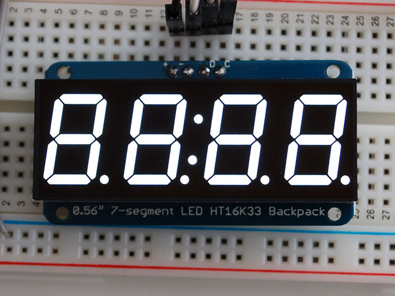
This version of the clock uses these 0.56" 4-digit LED displays, one per bus line and stop of interest. My clock happens to include four (two bus lines, two directions)…you can have up to eight, but for many people a single display will suffice — the bus that’s heading to work or school!
The point of this project is to create a bespoke transit clock tailored to your needs, aesthetic tastes and available tools and skills. Sure, I’ll show you what went into mine…but I’ve got decades of accumulated tools here and you’d spend ridiculous sums trying to emulate it exactly. Don’t do that. Design the clock that best serves YOU.
Parts from Adafruit:
- Feather HUZZAH ESP8266 WiFi microcontroller.
- 0.56" 4-digit 7-Segment Display w/I2C Backpack — one per bus line & stop — any color will do, they all work the same! Or mix and match, to color-code each bus line. Personally I liked the look of the white ones, but these (and the blue ones) are a couple bucks extra. There are also 1.2" backpack/displays in a few colors, if you need extra large type. In either case, make sure to get the 7-segment displays with I2C backpack, not just the “raw” display!
- Perma-Proto PCB. For a clock with just one or two displays, you might not need this!
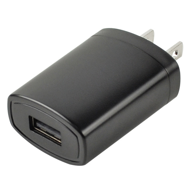
- Power source. You have MANY options here. It’s usually easiest to power the ESP8266 via the USB port…since I’ve got lots of spare USB cables and phone chargers, I upcycled one of those, but otherwise consider:
- 5V 2.4A Switching Power Supply w/6' MicroUSB cable -or-
- 5V 1A USB port power supply -plus- a USB A-to-MicroB cable or this nifty 6' USB Power-Only Cable with Switch.
(If using one of the power-only USB cables/supplies mentioned above, you will also need a “normal” (power data) USB A-to-MicroB cable for uploading code to the microcontroller.)
Other Items You’ll Need
At the very least, you’ll need the usual electronic project bits likewire and soldering paraphernalia.
For the initial code setup, you’ll need a computer that can run Python scripts from the command line…some systems (Linux especially) may already do this “out of the box,” but for others you may need to set this up on your own. That’s beyond the scope of this guide and you’ll need to acquire Python (it’s free) and read up on the basics elsewhere.
Beyond that, it’s all up to you how you’d like to present this. I went a bit overboard with 3D printing, laser cutting and even some toner-transfer trickery. Design your own case, or even just prop the bare LED display up on a shelf, it’s all good!
Circuit
In simplified schematic form, here’s what we’re aiming for:
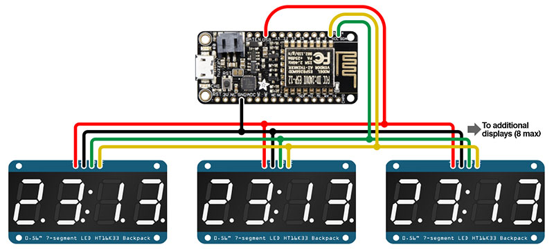
There’s just four connections between the Feather board andeach I2C display backpack:

For a single-display clock, it’s super simple, just four wires between the boards. With multiple displays, you can either try a multi-way splice, or it’s usually easier and more robust to use a piece of a Perma-Proto board to distribute power and signals to multiple points (I’ll show an example of this on the “Enclosure” page).
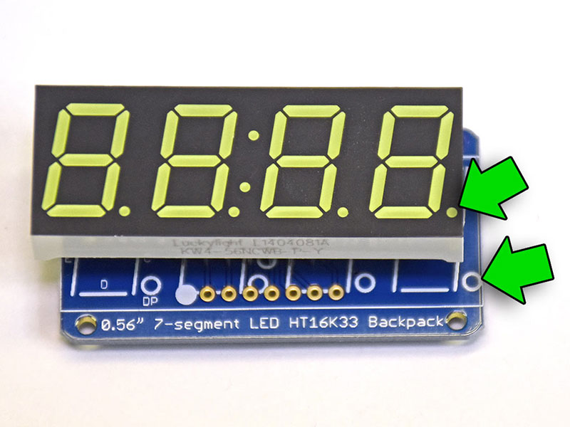
The 7-segment display/backpacks require some soldering. It is vitally important that the display be correctly oriented atop the backpack PCB! Use the decimal point markings (or the colons (:) on the 1.2" displays) as an indicator. The IC chip should be visible on the back of the assembly, NOT covered by the display.
If you get the orientation wrong, the display will not work. You’ll need to desolder all of the pins and re-assemble it correctly.
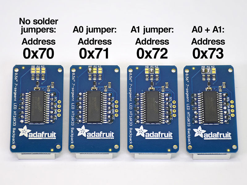
With multiple displays, each must be assigned a unique “address” using the A0, A1 and A2 solder jumper pads on the back:
The default, with no solder pads bridged, is address0x70. Bridging the A0 pads will add 1 to the address. Bridging A1 adds 2, and A2adds 4. This allows a maximum of 8 distinct combinations.
Take note of what address you’ve assigned each display — you’ll need this information later to configure the software.
After soldering the display(s) to the backpack(s), you can trim the wires so they don’t poke out the back as much.
You don’t have to wire up the displays to the Feather board yet (I’ll do that on the “Enclosure” page)…lets get the software side set up next, confirm we can access the network before snaking lots of delicate wires around inside a case.
Software
If this is your first time using the Feather HUZZAH ESP8266, you’ll want to begin with our guide for setting that up. There’s some software to install and a few persnickety items to be selected just right in the Arduino IDE:
Using the Feather HUZZAH ESP8266 with the Arduino IDE
To confirm that you have the driver installed and IDE properly configured, load the basic “blink” example sketch, edit the LED pin number to pin 0, then try uploading to the board. If it won’t cooperate, work carefully through each of the steps in the guide linked above.

Once the ESP8266 board is confirmed working, you’ll then need to install a few libraries. In recent versions of the Arduino IDE, this is done through the Library Manager (Sketch→Include Library→Manage Libraries…)
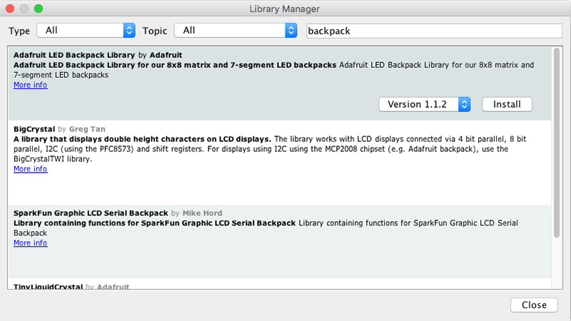
Search for and install the Adafruit LED Backpack library andAdafruit GFX. If the TinyXML library is available through the Library Manager, install that too. If it’s not, you’ll need to download and install that library manually (uncompress and move folder to documents/Arduino/Libraries, then restart the Arduino IDE).
Downlaod TinyXML Arduino library from GitHub.
The TinyXML library already includes our NextBus Arduino sketch. If the library’s properly installed, you can access it from the rollover menus: File→Sketchbook→Libraries→TinyXML→NextBus.
Software Config
Let’s now configure the system for your personal needs. You probably have a short list of bus stops and routes that are particularly relevant from your house, office or hackerspace.
The NextBus servers use a series of special “tags” (unique identifier strings) for naming transit agencies, routes and stops. The routefinder.py script (in the TinyXML/examples directory) helps uncover the correct tags and outputs them in a format that’s easily copied into the Arduino sketch.
routefinder.py requires Python to run. It’s launched from the command line:
Copy Code
python routefinder.py
Since it’s used just a few times for setup, routefinder.py isn’t very glamorous to look at…simply text-based with numeric prompts. The lists it displays are sometimes long, so it’s best run from a terminal with scroll-back capability.
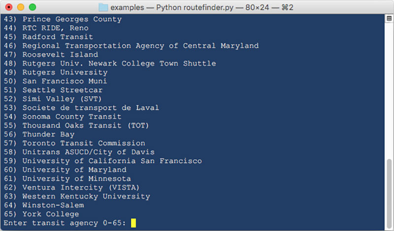
You’ll be prompted for a transit agency, route numer, direction and stop. The script then spits out a line of text similar to this:
Copy Code
COPY/PASTE INTO ARDUINO SKETCH:
  { 0x70, "actransit", "210", "0702630" }, // To Union Landing Shopping Center
Copy and paste the resulting line (in parenthesis) into the NextBus Arduino sketch. You’ll see there’s a list of routes near the top of the program:
Copy Code
  { 0x70, "actransit", "210", "0702640" }, // Ohlone College
  { 0x71, "actransit", "210", "0702630" }, // Union Landing
  { 0x72, "actransit", "232", "0704440" }, // Fremont BART
  { 0x73, "actransit", "232", "0704430" }  // NewPark Mall
The first item on each line is the I2C address of the corresponding display, set with solder jumpers as described on the “Circuit” page. The formatting of these lines is very persnickety! Make sure to get all the quotes and curly-braces right.
Run routefinder.py again for each stop and route you want arrival times for, copying the output into this list, and editing the I2C address for each.
Next, look for these two lines near the top of the sketch, and edit them with your WiFi network name and password:
Copy Code
char ssid[] = "NETWORK_NAME",     // WiFi network name
     pass[] = "NETWORK_PASSWORD", // WiFi network password
Then, a few lines down, there’s this line:
Copy Code
#define MIN_TIME 5 // Skip arrivals sooner than this (minutes)
This is a time threshold, in minutes, below which the clock just won’t even show expected arrivals. This is on purpose and by design. I know about how long it takes me to walk to my bus stops, allowing a couple minutes’ wiggle room for varying traffic and jumps that occasionally occur in NextBus’ predictions. I do not want even the temptation of rushing for a bus that I may or may not catch…the whole point of this design was to avoid stress and accidents. So those too-soon predictions are just thrown out, depending on this value.
Upload and Test
If your board settings haven’t changed since running the “Blink” sketch, you should be able to just click “Upload” now and have the sketch transferred to the ESP8266 board. If not, go back and review the board settings described here, confirm that all three libraries (Adafruit_LEDBackpack, Adafruit_GFX and TinyXML) are correctly installed, and make sure the syntax is correct for any changes you’ve made to the NextBus sketch.
If it uploads successfully, open the Serial Monitor window to see that the board’s connecting to your wireless network and is contacting the NextBus server. If not, double-check the network name and password near the top of the code.
If you don’t have the LED Backpack displays connected yet (I’ll show this on the next page), it’s not much to look at, but the Serial Monitor at least lets us know that the networking side is good!
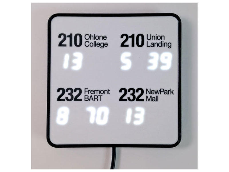
This is all a bit much, with the toner transfer and everything. I was after a particular “crisp” aesthetic with the Helvetica lettering. Maybe a Sharpie pen is all you need!
I’ve collected the various mixed-media files used here — laser cutting, laser printing, 3D printing, etc. — on Thingiverse. If you can adapt all or part of this to your own personal project, have at it:
Download Files from Thingiverse
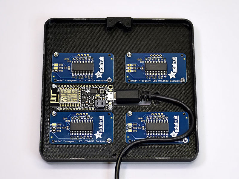
All the electronics are installed on another 3D-printed piece, a sort of bracket that fits inside the frame and behind the front face.
Before soldering, everything was test-fit first. The various boards are held in place by M2 machine screws (there are four mounting holes, but two screws were sufficient — these are not load-bearing). Though for this application, since nothing will be seen from the front, even hot-melt glue would work fine.
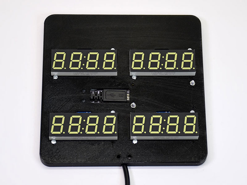
Keep track of the displays and their I2C addresses, since each is uniquely identified in the code. And remember when viewed from behind that the positions will be flipped left-to-right…the top-left display on the front of the clock will be on the top-right from behind.
Adafruit Perma-Proto boards aren’t just for whole circuits…they can also be cut apart using tin snips or a scroll saw, and cleaned up with sanding.
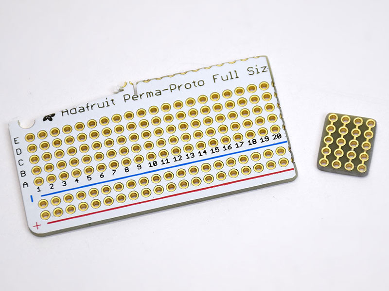
With five boards total in this design — four displays plus the Feather board — and four wires ( , –, D and C) connected to each, a little 4x5 square is all we need. An inconspicuous spot in the case was found, wires were measured to fit, stripped and soldered to the Feather board first.
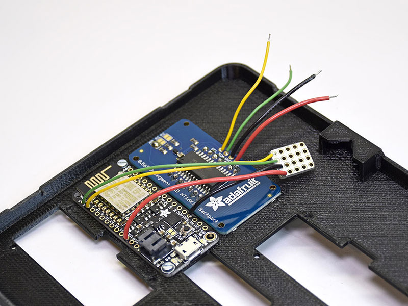
Wires to each display were then measured, stripped and soldered to each display board, then to our little distribution board. So tidy!
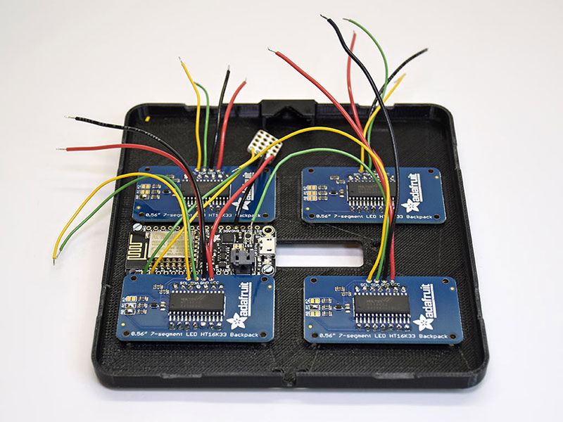
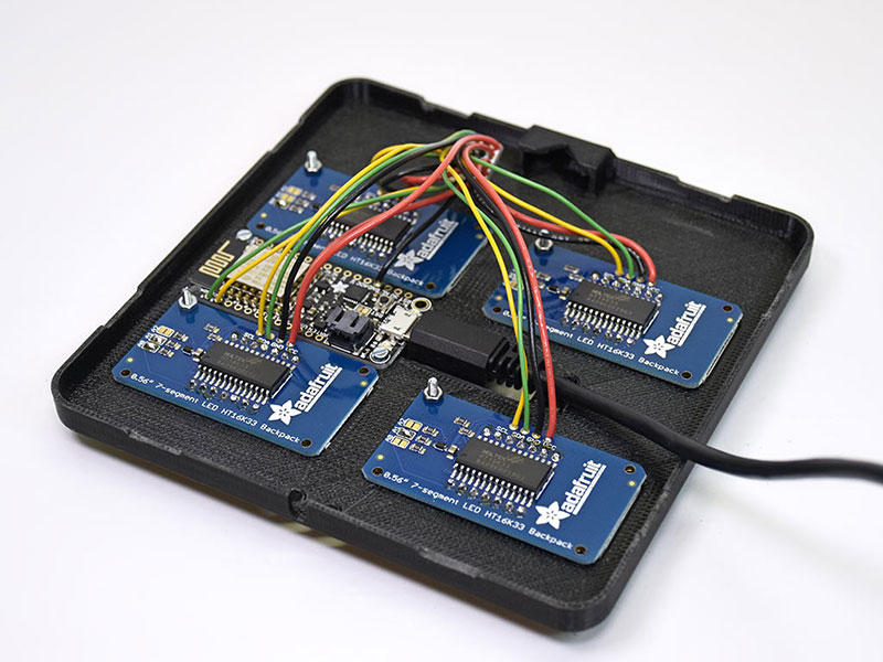
Before finalizing everything…plug in for a test run!
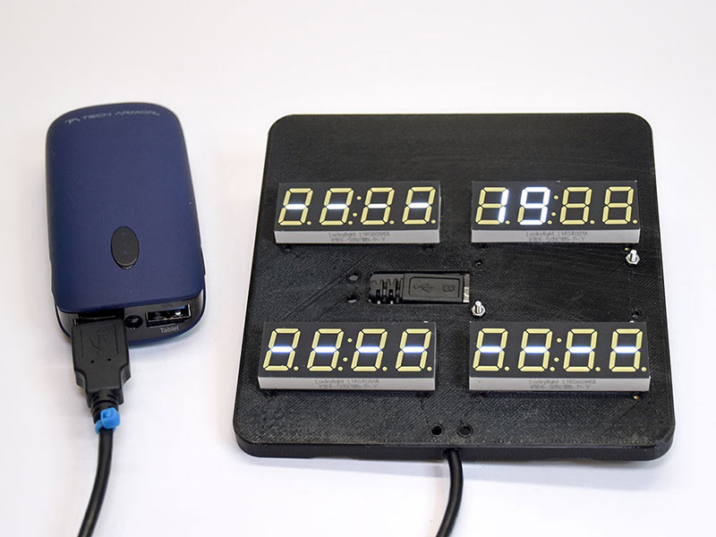
It was late at night when I tested this…only a single bus route was running…but I could see the code was animating each display at the right time, so any other trouble at this point would just be a software configuration issue.
? ~ Nothing lights or happens at all?
- Unplug USB and check your wiring and soldering connections for any short circuits… and – may be crossed, or there may be a solder bridge on the Perma Proto board or one of the displays.
- Has the NextBus sketch been uploaded to the ESP8266 board?
- Confirm D and C (data and clock) are connected to SDA and SCL on the Feather board, respectively.
- Do the I2C addresses of each display match the table in the Arduino sketch?
? ~ Only some of the displays work, or the displays show nonsense?
- Is the 7-segment display installed in the correct orientation on the I2C backpack board?
- Confirm D and C (data and clock) connect to SDA and SCL on the Feather board, respectively.
- Do the I2C addresses of each display match the table in the Arduino sketch?
? ~ The displays are in the wrong order/positions?
Probably easiest to fix in software at this point. Take note of the positions and the I2C address that each display is assigned, and rearrange the values as needed in the Arduino sketch.
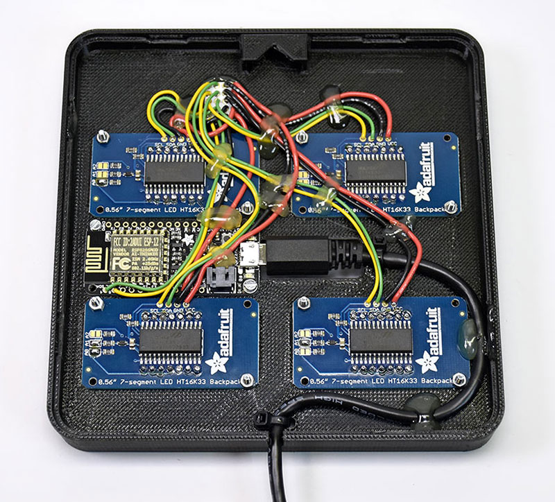
Once everything’s tested and confirmed working, mounting screws are installed and tightened, cable ties are added to the USB cord in a couple places for strain relief, and all of the wires are carefully routed to lay flat, held in place with dabs of hot glue. When that’s all cooled off, the internals can then be clicked into place inside the frame.
Hang it up, plug it in and always know when the next bus is due!




 中国
中国