Build an Ultrasonic Intruder Alarm with LED Indicator
2022-12-07 | By Maker.io Staff
License: See Original Project
You probably have seen robotic projects with a device that looks like a pair of eyes and wonder, what is that part? Well, you do not have to wonder because, in this project, you will learn how to build an Ultrasonic Intruder Alarm using an Arduino Uno and a few off-the-shelf electronic components. In this hands-on project, you will learn how to wire an ultrasonic sensor to an Arduino. Further, while wiring the sensor to the Arduino, you will build an electronic tape measure to allow adjusting the intruder detection distance with your electronic alarm unit. To build the Ultrasonic Intruder Alarm with an LED indicator, you will find the electronic components required to build the project at the Digikey SchemeIt BOM (Bill of Materials) website. Here is the electronic circuit schematic diagram and BOM link for the Ultrasonic Intruder Alarm project; https://www.digikey.com/schemeit/project/ultrasonic-intruder-alarm-6ce7fdbfe769417da2071905044d13bb/. The functional concept of the device is to provide an audible and visual alarm upon detection of a human within a specified sensing zone.
Ultrasonic Intruder Alarm with an LED Indicator device Concept Diagram
The four main subcircuit components to build the electronic intruder alarm device include an ultrasonic sensor, an Arduino Uno, a piezoelectric buzzer, and a LED circuit. The LED circuit consists of a series limiting resistor and a discrete LED. A block diagram showing the electrical wiring relationship between the subcircuit components is shown below.
The Ultrasonic Intruder Alarm Block Diagram
How Does an Ultrasonic Sensor Work?
A device that uses ultrasonic sound waves to measure an object’s distance is called an ultrasonic sensor. Ultrasonic sensor transducers send and receive ultra-high frequency sound waves to obtain an object’s distance or proximity. The transducers are a microphone and a speaker. The ultra-high frequency sound waves are reflected from an object’s surface, creating a unique echo pattern.
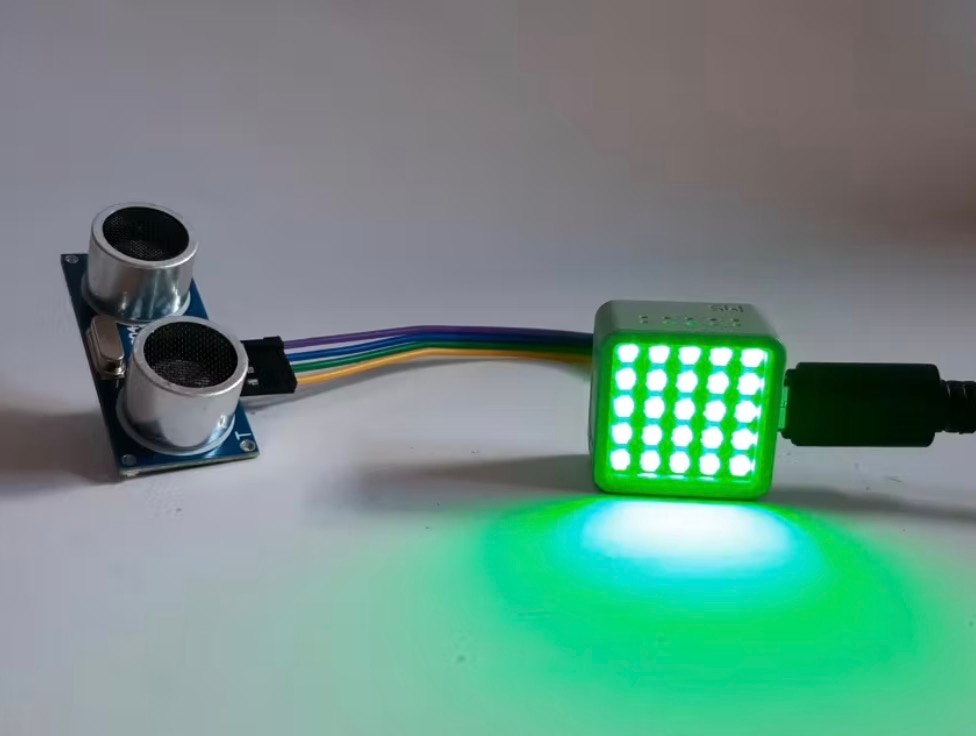
An HC-SR04 ultrasonic sensor with transducers.
The below image illustrates the ultrasonic sensor’s ultra-high frequency sound waves being reflected from an object’s surface.
Sent and reflected waves: ultrasonic sensor basic operation.
Wiring an ultrasonic sensor to an Arduino (TinkerCad Circuits)
With a basic understanding of how an ultrasonic sensor works, you are now ready to wire the device to an Arduino. To explore the operation of the ultrasonic sensor, you can build a virtual functional circuit using TinkerCad Circuits. TinkerCad Circuits is a free online circuit simulator that allows a variety of electrical and electronic circuits to be simulated prior to wiring them on a real breadboard. You can even test Arduino projects (including the code) with TinkerCad Circuits. You can gain valuable electronics knowledge through experimentation prior to committing the building the physical circuit.
An example online ultrasonic sensor-Arduino TinkerCad Circuit
Wiring a real ultrasonic sensor with an Arduino on a breadboard
You can use the ultrasonic sensor-Arduino circuit built in TinkerCad Circuits or the electrical wiring diagram shown below to build your intruder alarm device. You can place the ultrasonic sensor as shown on the breadboard and use jumper wires to complete the wiring of the sensing device to the Arduino.
The electrical wiring diagram for the Ultrasonic Intruder Alarm with LED indicator
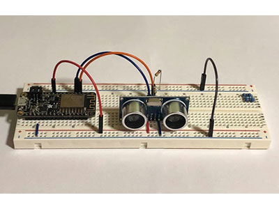
Here’s the final prototype built using discrete components to create the Ultrasonic Intruder Alarm with an Arduino Uno.
The final Ultrasonic Intruder Alarm prototype
The HC SR04 ultrasonic sensor 4-pin terminals that attach to the Arduino are included in the previously linked schematic diagram. As an additional reference, the below wiring table will assist in wiring the connections between the Arduino Uno and the ultrasonic sensor.
The 4-pin wiring connection of the Arduino Uno to the ultrasonic sensor.
Congratulations, you have just wired an ultrasonic sensor to an Arduino. You are now ready to install (upload) the ultrasonic sensor code to the Arduino Uno.
The Ultrasonic Intruder Alarm code
Attach the Arduino Uno to your desktop PC or laptop computer using a USB cable. You can type the code into the Arduino Integrated Development Environment (IDE) using the code shown below or you can download the code. With the code displayed in the Arduino IDE, you can upload the code by clicking the horizontal arrow.
#define TRIG_PIN 11
#define ECHO_PIN 10
int LEDpin = 13;
SR04 sr04 = SR04(ECHO_PIN,TRIG_PIN);
long a;

void setup() {
  pinMode(LEDpin, OUTPUT);
   Serial.begin(9600);
   delay(1000);
}

void loop() {
   a=sr04.Distance();
   Serial.print(a);
   Serial.println("cm");
   delay(1000);
   if(a < 200) {
     digitalWrite(LEDpin, HIGH);
   }
   else{
     digitalWrite(LEDpin, LOW);
   }
}
Placing your hand or object in front of the ultrasonic sensor will turn on the LED indicator and sound the piezo buzzer. Here is a short video illustrating the Ultrasonic Intruder Alarm’s operation; https://youtu.be/X5-RfRhKBwk. Additionally, by opening the Serial Monitor within the Arduino IDE, you should see distance data scrolling down in the Arduino IDE. Below is an example of the data from the distance measuring circuit. Place a small scale or ruler between the ultrasonic sensor and the object’s distance to measure. How accurate are your readings compared to the actual distance measured? This integrated measurement feature may be used to adjust the sensing distance of the object or intruder you want to detect. You have successfully built an ultrasonic intruder alarm. Congratulations again!! You can detect and observe a variety of objects and their measured distance with an electronic detection device.
An example distance measuring session with an electronic tape measure feature.


