制造商零件编号 CYPD3177-24LQXQT
IC USB TYPE-C PORT CONTROL 24QFN
Infineon Technologies
Most of the time, the quickest way to build a circuit is using a breadboard. However, once you have your circuit built, you need to be able to power it on the breadboard. To do that, I usually use a breadboard power supply that plugs right into the rails of the breadboard. I'm going to design and build my own breadboard power supply, but instead of using a barrel jack or a USB mini or micro connector, mine will have USB-C power delivery.
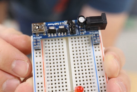
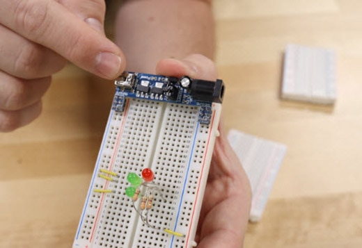
I've been using breadboard power supplies for years and they work great, but most of the time, they use a DC barrel jack or a USB mini or micro connector. I don't usually have a DC barrel plug sitting around ready to use to power a circuit, however, I'm much more likely to have a USB-C power supply nearby.
One thing I like about the power supplies that I already have is that they have a selection jumper. I can choose between 5V from the USB connector or 3.3V from the onboard voltage regulator. The cool thing about this design is that the two rails are independent. One could be set to 5V and the other to 3.3V. Since my design will use USB-C power delivery, I’ll have more flexibility with voltages between 5V and 20V. To get the 3.3V I'm still going to have to use a voltage regulator of some sort.

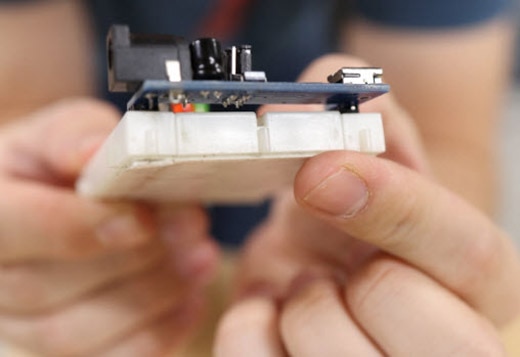
Using USB-C to get those higher voltages is tricky because I need to use a power management IC to negotiate the voltage I’m asking for. As I look closer at this example design, I like how it's notched out so that the PCB isn’t covering up any of the tie points of the breadboard. In my design, I want to copy that feature. However, there's a big drawback to this example design and I want to fix it. The power supply is cantilevered over the edge of the breadboard. In my experience, when I plug things in, the power supply sort of wiggles around, and sometimes it can come loose. My plan to fix this problem is to 3D print a little base plate that provides more support for the PCB.

First, I need to figure out which chip I will use for the USB-C power delivery part. A quick search on DigiKey brought me to the Infineon CYPD3177. This chip will handle all of the negotiations for USB-C power delivery. I’m excited to find that they have an evaluation board that will help me design this power supply. When I design something like this, I always like to check to see if there's a reference design or even an evaluation board that I can glean information from.

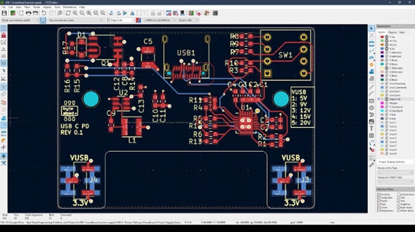
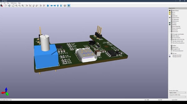
With this evaluation board in hand, it is easy for my team and I to design a PCB around it. We use a software called KiCAD and one of the things I like about KiCAD is that I can view my PCB as a 3D model. Some of the parts we use in this design, for example, the USB connector, don’t have an actual 3D model in the software. So, I just hop on the DigiKey website, download the 3D model, and insert it into the footprint. We decided to make this board four layers instead of the usual two. This is to make it easier to route all of those different voltage buses and to give us room for more copper zones to have higher currents. GitHub repository can be found here: https://github.com/bytesizedengineering/USB-C-Power-Delivery-Breadboard-Power-Supply

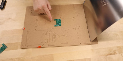
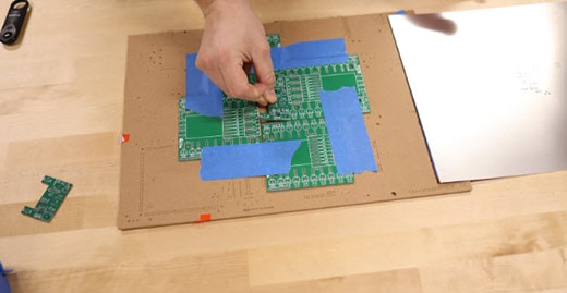
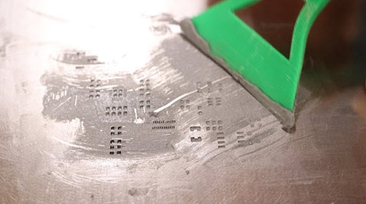
Next, I need to order the PCBs. No matter how many times I've designed PCBs, it's always an exciting moment when I get to open up the box and see the board in real life for the first time. When I ordered my PCB, I also ordered a solder stencil for it as well. This will help me apply solder to all the little pads rather than having to dab them on individually. To help me get everything aligned, I’ll grab a few extra PCBs from an old design, and I create a little perimeter around my board. I have five of these PCBs to make, and lining up the stencil takes a bit of time. Rather than having to align it five times, this makes the alignment process repeatable. With this jig, I can insert a blank board and apply the solder paste, remove it, stick in the next one, and have it exactly line up every time.
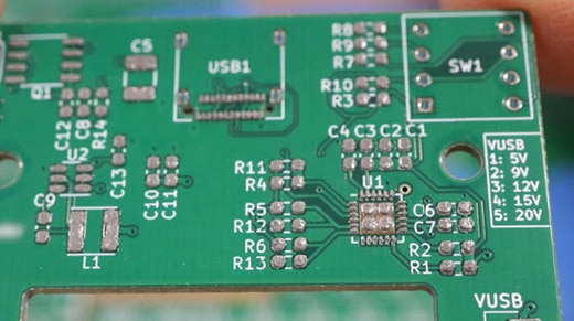
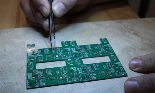
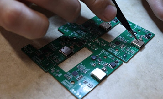
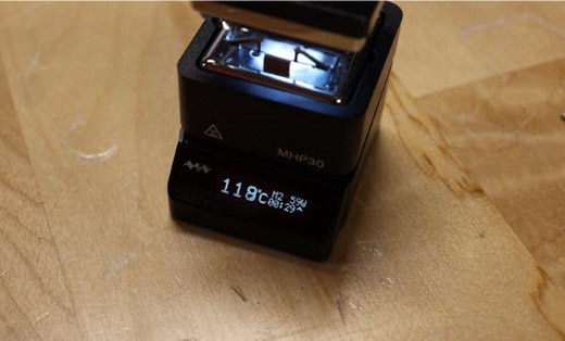
There is something therapeutic about assembling a PCB. I love getting out a box of parts, sitting down at the microscope with my headphones in, and just getting to work. Am I the only one who likes doing this? Now that I have all the parts placed, it's time to reflow the board. Last year I built a solder reflow oven using a toaster oven. But this time I wanted to try a different tool, so I ordered the MHP30 (FIT0888) from DigiKey. I’ll use the solder paste reflow data sheet to set the three temperatures and then use the onboard timer to let me know when it is time to change to the next preset. This mini hot plate makes this task super easy, and I think the results are great. I'll never get tired of watching solder paste change from solid to liquid. It's so satisfying.
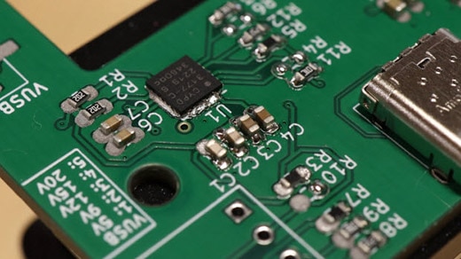
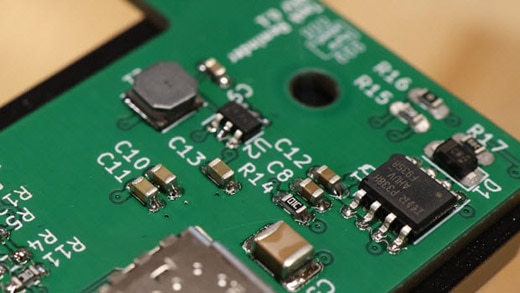
Next, I’ll design, and 3D print a little enclosure. It takes iteration, after iteration, after iteration, but I finally get something I think I'm happy with. Now I'm ready to install the PCB inside the enclosure. The last piece is the voltage dial. Using the dial, I can select what voltage I want on the output rails. If you're familiar with breadboards, you'll know that they aren't symmetrical. So this can only go on one side of the breadboard and not the other. I printed the plus and minus voltage rails onto the enclosure to make them easier to identify.
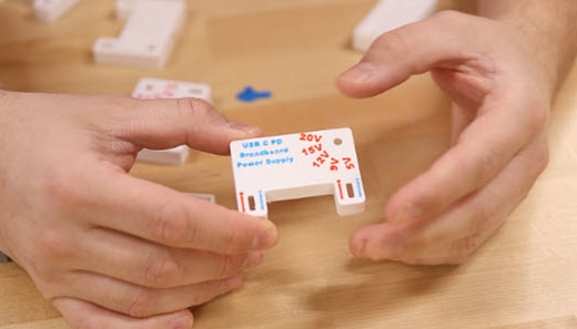
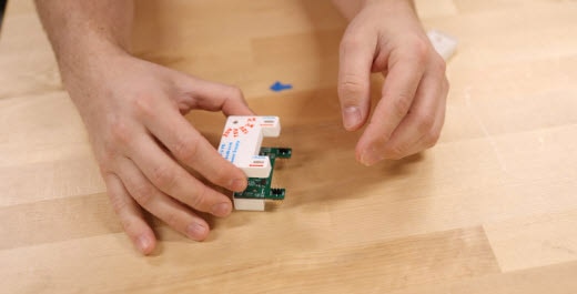
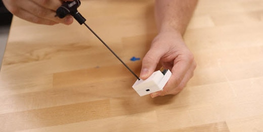
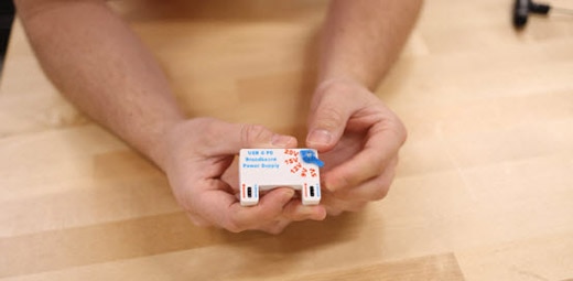
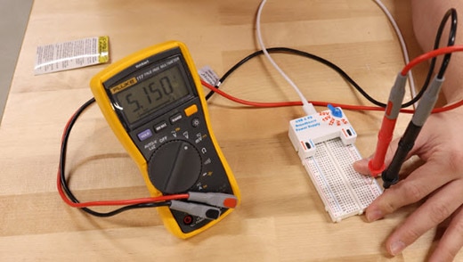
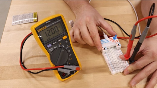
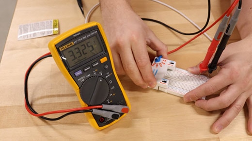
Now I can plug in a USB-C cable that is connected to a power delivery adapter. Here I have 5V on the rails. If I change the selection arrow to 9V, it adjusts to 9V, and the same goes for 12V, 15V, and 20V. But if I want 3.3V, all I need to do is change the selection jumper and I will get 3.3V on the output. Both of these rails work independently so I can either have VUSB on the rail or I can have 3.3V. I also solved the problem of having the power supply coming out by adding a base to the case that reaches my table for support. This thing is solid, and it doesn't wiggle out.
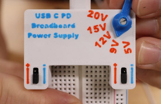

Now let's talk about the things I don't like about my design. The first thing I want to change in the next revision is using through-hole headers instead of surface-mount headers. I can make this design much thinner and more stable by using through-hole headers instead of surface mount. The next thing I do not like is using that selection jumper. I could have achieved the same result by using a switch instead of a jumper.
But you always have to have a version one of any product design, and I'm happy with how this turned out. I'm excited to start using it and prototyping circuits. I have a lot of ideas on how I can improve this. I might want to add a microcontroller or possibly a display and some LEDs to make this even more functional.
