制造商零件编号 WBNCC633731-2OZ
NO-CLEAN FLUX CORE SOLDER, 63/37
SRA Soldering Products
Hand Tools Solder / Desoldering Raspberry Pi MCU XIAO
If you’ve got a working solderless breadboard prototype of your project, the next logical step is to make it more permanent by translating your project to a solder-type breadboard. Soldering your circuit will allow you to make your circuit more durable and smaller, and it’s a smart step on the way to designing your own circuit board and enclosure if you choose to do so.

The first step I suggest is to draw a circuit diagram. You can sketch it on paper or make it on the computer, but the important thing to do is draw every connection and label each component.

Some circuit software like Fritzing and Tinkercad Circuits allow you to represent the breadboard as well, so you can start by drawing exactly what you see. But the circuit diagram doesn’t have to have all the parts laid out exactly how they are on your breadboard; instead, it documents the electrical connections required to make the circuit function.

Here’s a diagram representing the webcam privacy device we prototyped together during a previous episode. The diagram shows the various components connected to where they go, but the breadboard power and ground busses and various rows aren’t always depicted. Abstracting your design to a diagram is always smart, and it’s absolutely necessary if you want to get your circuit manufactured.
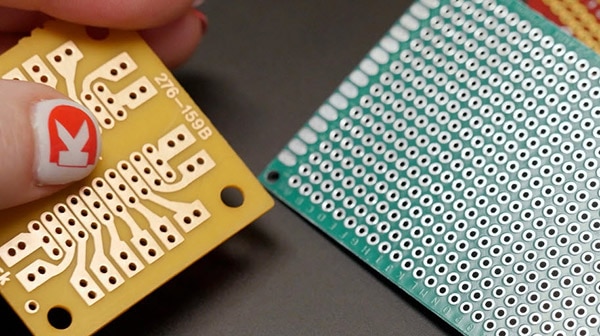
Once you have an accurate diagram, you can build a new version of your circuit on a solder-type breadboard, also called perfboard. This stuff has plated through holes and comes in a variety of configurations.
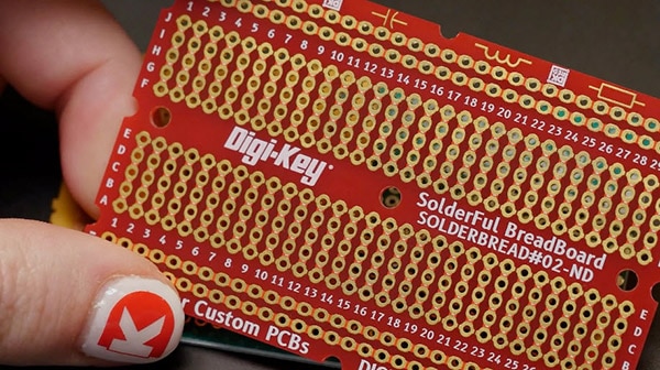
Perhaps the most useful type for beginners is the kind that takes the same format as the inside of a solderless breadboard (DKS-SOLDERBREAD#02-ND), so you can replicate the connections from your prototype exactly, and they end up looking similar enough to compare easily.

They even come in the shape of an Arduino shield so you can plug your circuit board right on top.
Here are some of my favorites:

Often times this is when you’ll switch to a smaller Arduino board format, too. Most basic Arduino code will run just fine when you put it on a different board with the same or a similar microcontroller, with the caveat that the pin numbers might need to be updated to match the appropriate corresponding pins on the new board.

So, for example, I may prototype a NeoPixel project on an Arduino Uno using pin 6 for data…
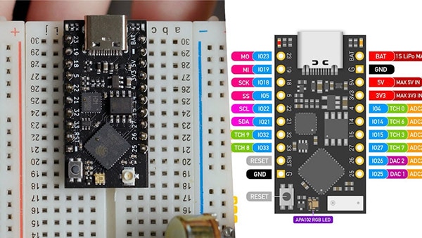
…But when I switch to the TinyPico (1778-TINYPICO-U-01-ND), I’ll have to change my code to reference a different pin, since there is no pin 6 available to me.

However, not all boards are created equal, so be sure you have enough pins to move your circuit over. For example, ESP8266 boards only have one analog input pin, so it’s an unsuitable substitute for a project with more than one analog input.
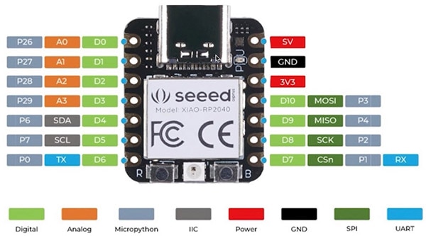
You can usually find a pinout diagram, like this one for the Seeed Xiao RP2040 (1597-102010428-ND), in the product documentation that explains what each pin can do.
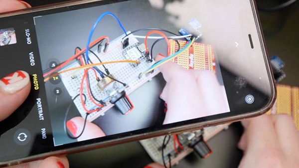
If you’re able to acquire two of every component in your circuit, you can have the luxury of referencing your solderless prototype as you build the soldered version. If not, you can unplug and transfer over the components one at a time, leaving the wires in place in case you need to reference them later, or just use a photo to refer back to.
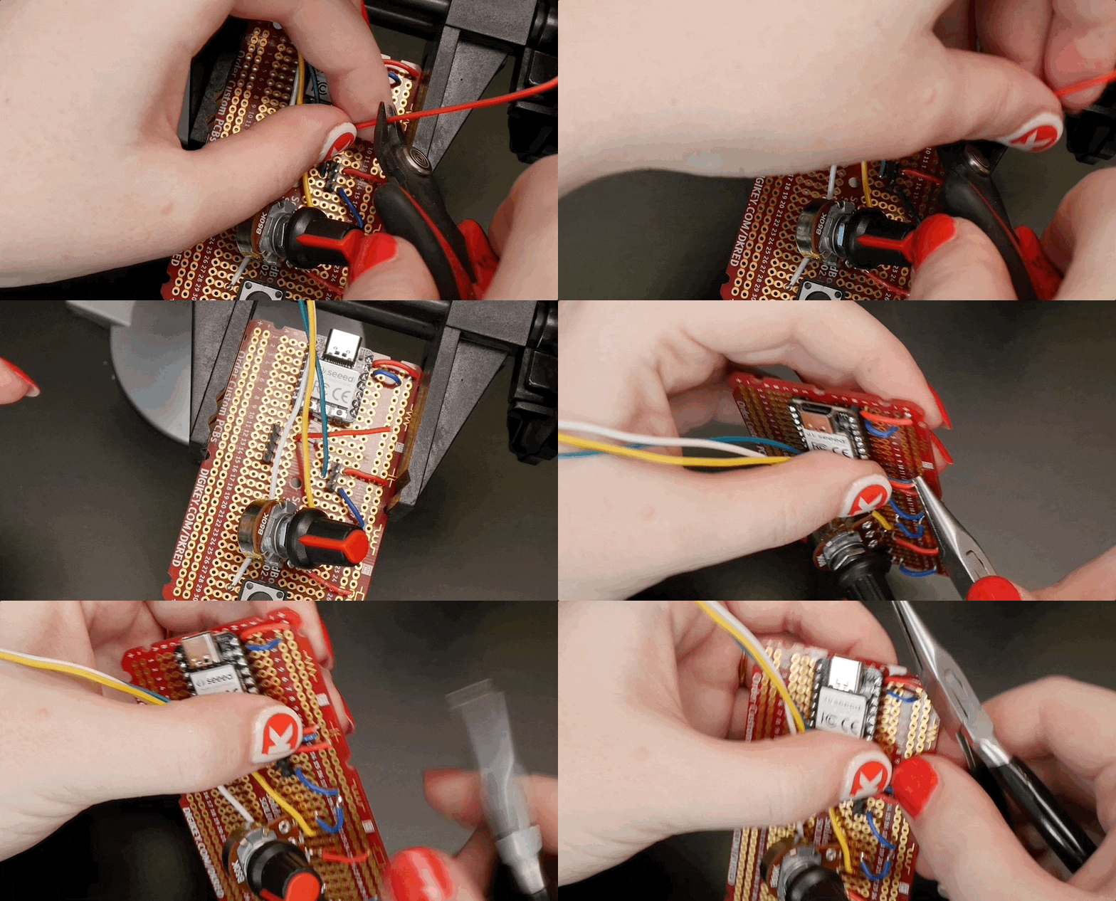
So that’s the concept, but in practice, there’s a lot of physical construction to do to put it together. You can learn how to solder in a previous episode of this series, then get your practice in by building your circuit. It’s a lot of trimming, stripping, and tinning wires, plugging them into the board, flipping it over, soldering, on repeat until everything’s hooked up.
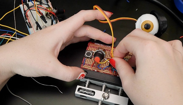
I like to use a little circuit board vise (1528-1747-ND) to hold it steady. You may also want to add longer wires to your components to better suit their final use case. For example, I made a long extension for my servo motor so the privacy device controller can sit on the desk while the motor perches on top of the monitor.
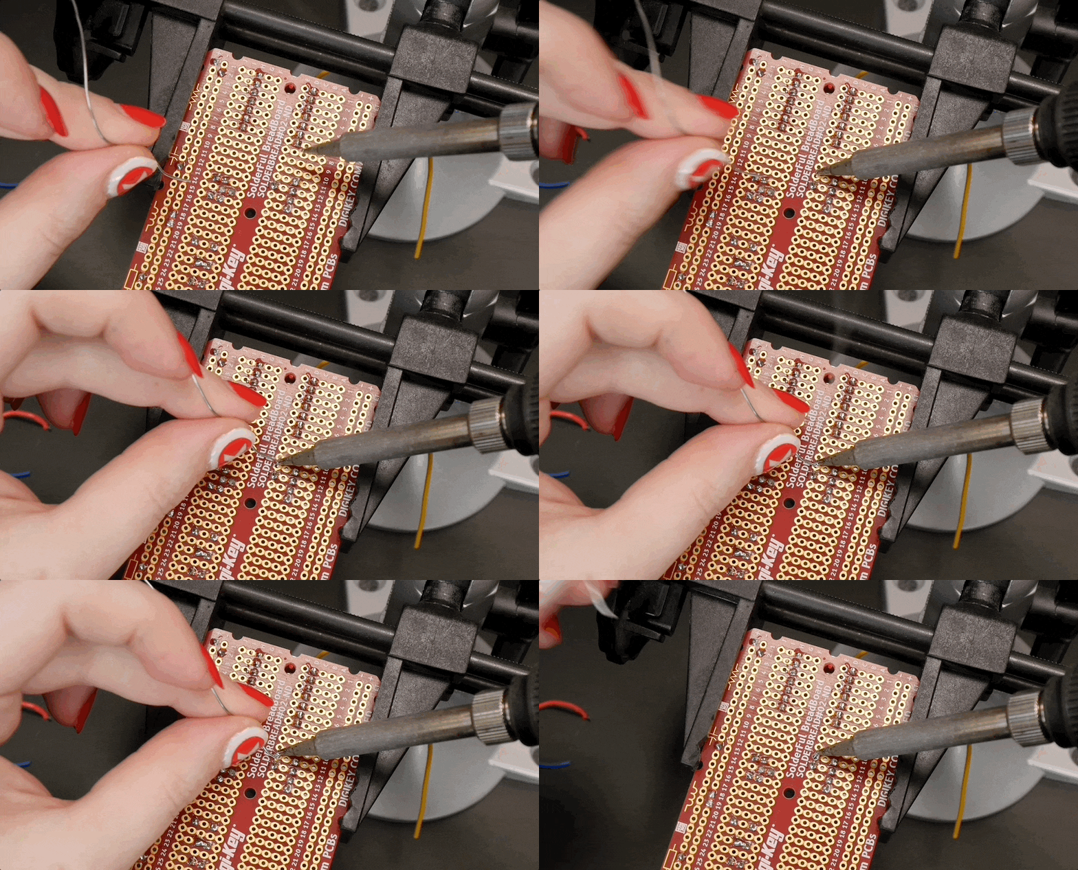
Soldering your whole circuit will probably take a while, so check your posture and ventilation, and remember to wash your hands when you’re done. If you make a mistake, hopefully it will be easy to spot by checking against your diagram and solderless prototype, in addition to the troubleshooting steps mentioned in our previous episode on the topic.

When checking continuity with a multimeter on a soldered circuit, try to probe the component lead or wire itself to avoid being fooled by a cold solder joint.

Once you’re all done, I hope you feel the satisfaction of making something that, in my opinion, feels very much like a completely homemade gadget. You’ll also want to put your circuit inside an enclosure, which will be the topic of a future episode.
You may now also be incapable of watching movies and TV featuring DIY electronics without dissecting the realisticness of said props and set dressing. My apologies, unless you work in film and TV, in which case, you’re welcome.
You’re also ready to start learning to layout your circuit design as a printed circuit board, which you can learn more about in Shawn Hymel’s “Arduino Project to Product” video series.
Check out the rest of this series for even more information on building with Arduino!