Novel Buck-Boost Regulators Deliver Higher Efficiency, Handle More Power
投稿人:电子产品
2015-10-21
We know a buck-boost DC/DC converter is a reliable component that will deliver regulated output voltage under varying input voltage conditions that prevail in many industrial and automotive environments, including battery-powered products. For so many years, suppliers like Intersil, Linear Technology, Texas Instruments and Vicor, among others, have continued to improve the performance of these devices while expanding their product portfolios1,2.
Now, some of these suppliers have released new-generation buck-boost DC/DC converters with many unique features and functions to meet new challenges and overcome hurdles that previously limited their use. In addition, losses have been minimized to achieve very-high efficiencies with wider input and output voltage ranges and high-output current. High-frequency operations are also enabling best-in-class power density and transient response. As a result, these converters are being designed into a wide range of high-performance applications including computing, communications, industrial, LED lighting, and battery systems.
Variable regulated outputs
Vicor, for example, has expanded its buck-boost family with the addition of a new flexible buck-boost converter, PI3749, with a wide input voltage range. Its variable regulated output can be varied over a wide range with a very-high conversion efficiency of 98 percent. A member of the Picor Cool-Power ZVS family, it incorporates the company’s zero-voltage switching (ZVS) topology to minimize switching losses and maintain high efficiency over the specified input-voltage range of 16 V to 34 V. The converter’s regulated output voltage can vary from 12 V to 34 V while output current can go as high 11.5 A for power delivery of over 200 W.
The high-density buck-boost converter comes in a 10.0 x 14.0 x 2.56 mm LGA system-in-package (SiP) that integrates a controller, four power switches, and associated support components as shown in Figure 1. Consequently, the PI3749-00 requires only an external inductor, resistive feedback divider, and minimal capacitors to form a complete DC/DC switching-mode buck-boost regulator.

Figure 1: Vicor’s latest buck-boost regulator comes in an LGA system-in-package (SiP) that integrates a controller, power switches, and support components.
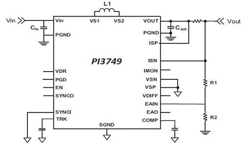
The output voltage can be adjusted by feeding back a portion of the desired output through a voltage divider to the error amplifier’s input (Figure 2). Equation 1, taken from the product data sheet can be used to determine resistor values R1 and R2 of the voltage divider.
As described in the data sheet, the R2 value is selected by the user. The supplier recommends 1.07 kΩ (1%) resistor value for R2. Consequently, if you need a 24 V output, you can use equation (1) to calculate R1. Once R1 is calculated, the user should select the nearest resistor value available, according to the maker. Hence, for this example, using equation (1), R1 turns out to be 14.03 kΩ. So it is recommended to use 14.0 kΩ with 1 percent tolerance.

Figure 2: To complete a DC/DC switching-mode buck-boost regulator, PI3749 requires only an external inductor, resistive feedback divider, and a handful of input and output capacitors.
The ZVS architecture also enables high-frequency operation while minimizing switching losses and maximizing efficiency. The high-switching frequency operation reduces the size of the external filtering components, improves power density, and enables very fast dynamic response to line and load transients. Using a 480 nH external inductor (L1) with external capacitors CIN = COUT = 20 pF and 800 kHz switching frequency, the product data sheet offers efficiency performance for a 24 V-output solution over an input voltage range of 16 V to 34 V (Figure 3).

Figure 3: Efficiency versus output current for a 24 V-output solution using Cool-Power ZVS buck-boost regulator PI3749-00. The input voltage range for this design is 16 V to 34 V.
It is observed that the peak efficiency for the 24 V-output buck-boost converter is 98.5 percent at full-load of 7 A with 24 V input. It drops by a point to 97.5 percent when the input is 16 V or 34 V. Plus, the efficiency remains high across wide load variations. For instance, from mid-load to full-load the efficiency remains over 97 percent, which drops by a few points at low-load.
For higher output-current requirements, PI3749 can be connected in parallel by using single-wire current sharing without any additional components. According to the part’s data sheet, the buck-boost regulators will share the output current equally when pins EAO, EAIN, and SGND of each module are connected together, and the output ripple is not excessive.
More options
Similarly, Texas Instruments has launched a new four-switch synchronous buck-boost DC/DC controller LM5175 that achieves very-high efficiency with reduced EMI. Offering integrated drivers for N-channel MOSFETs, the buck-boost controller handles wide-input voltages from 3.5 V to 42 V, and regulates output voltages from 0.8 V to 55 V. Designed for a wide variety of buck, boost, and buck-boost applications from output power of a few watts to greater than 100 W, LM5175 employs a proprietary switching scheme to maximize efficiency in the buck-boost transition region. Plus, it utilizes current-mode control both in buck and boost modes of operation for better load and line regulation. The switching frequency is programmed by an external resistor and can be synchronized to an external clock.
According to the manufacturer, the buck-boost controller presents a robust gate drive (2 A at 7.5 V) that allows wide-input MOSFETs to switch faster and more efficiently. Additionally, the product data sheet shows that the controller offers optional hiccup mode short-circuit protection to prevent thermal runaway during extended load current faults, reducing thermal stress by up to 30 percent.
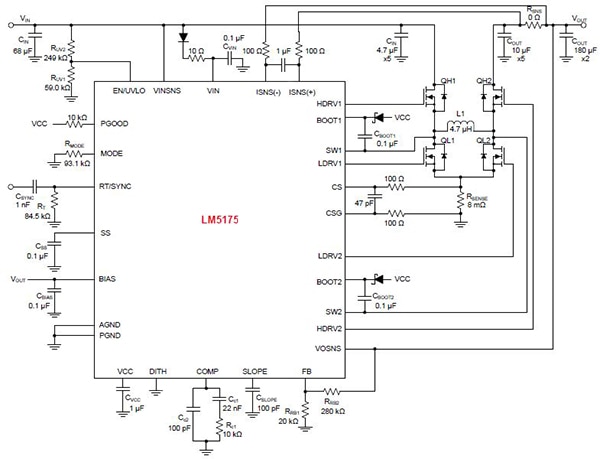
A typical buck-boost DC/DC converter using LM5175 controller operating from a wide-input voltage range of 6 V to 36 V and providing a stable 12 V-output voltage with current capability of 6 A is shown in Figure 4. The product data sheet indicates that the switching frequency for this design is 300 kHz and the mode of operation is continuous conduction mode (CCM) and hiccup. Likewise, selection of other external components (such as the inductor, input/output capacitors, sense resistor, slope compensation, and output MOSFETs) is explained in detail in the product data sheet.

Figure 4: LM5175-based buck-boost DC/DC converter schematic, operating from a wide-input voltage range of 6 V to 36 V with 12 V output at 6 A.
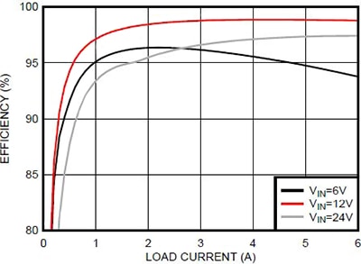
The efficiency response for the LM5175-based buck-boost DC/DC converter in Figure 4 with 12 V output is depicted in Figure 5. This efficiency curve is taken from the product data sheet. It is observed that for a 12 V input, the buck-boost provides peak efficiency of nearly 99 percent from mid-load to full-load. It remains as high as 95 percent even when the load is as low as 0.5 A. In the buck mode, with 24 V input, the efficiency drops to 97.5 percent at full-load, but remains around 97 percent from mid-load to full-load. By comparison, the efficiency drops faster at low-load in the buck mode. In the boost mode with 6 V input, the efficiency performance goes even lower at mid- to full-load. It gets better than buck mode in the low-load region.

Figure 5: Efficiency versus load current for the LM5175-based buck-boost converter with 12 V output. The input range is 6 V to 24 V.
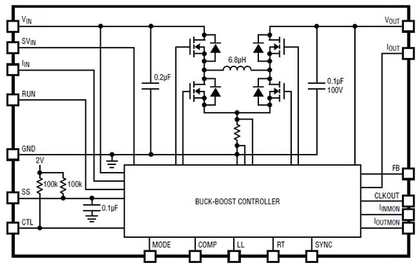
For higher input voltage, up to 58 V, with 4 A load current, Linear Technology has added a new member to its family of buck-boost μModule regulators. A complete switched-mode DC/DC converter, the LTM8056 offers an input-voltage range of 5 V to 58 V with the ability to regulate output voltages between 1.2 V and 48 V. In a compact overmolded ball-grid-array (BGA) package, it incorporates a switching controller, four power switches, an inductor, and supporting components as depicted in Figure 5. It delivers 4 A-load current and its switching frequency is selectable from 100 kHz to 800 kHz.

Figure 6: In a single BGA package, the buck-boost μModule regulator LTM8056 includes a controller, four power MOSFETs, an inductor, and supporting components.
In summary, to broaden the adoption of buck-boost DC/DC converters in a wide range of applications, suppliers continue to expand their portfolios with novel members that deliver higher efficiency across a wider input-voltage range with a wider configurable output. Besides offering higher efficiency, these new buck-boost DC/DC converters also handle higher power and offer features that add to the performance characteristics of the device.
For more information on the products discussed in this article, use the links provided to access product pages on the Digi-Key website.
References
- “New Buck-Boost DC/DC Converters Offer Jitter-Free Transition with High Efficiency” by Ashok Bindra, Electronic Products, August 11, 2015.
- “Buck-Boost DC/DC Handles Wide Input-Voltage Range” by Ashok Bindra, Electronic Products, July 30, 2013.
免责声明:各个作者和/或论坛参与者在本网站发表的观点、看法和意见不代表 DigiKey 的观点、看法和意见,也不代表 DigiKey 官方政策。


