Many Options for Building High Step-Down-Ratio Buck Converters
投稿人:电子产品
2015-10-06
Designing high step-down-ratio DC/DC power converters is not trivial, especially when converting from 48 VDC input to 3.3 VDC output and below, because maintaining high efficiency and density with minimal cost is challenging. Such DC/DC power converters are primarily needed in telecom systems and data-center computers with boards populated with modern DSPs, FPGAs, and ASICs requiring voltages ranging from 3.3 V and lower. To avoid building high step-down-ratio buck converters, designers have been using intermediate bus converters to further step-down the popular 48 VDC bus voltage in such systems to an intermediate voltage level of 24 V, 12 V or lower. That is adding another step-down stage to simplify the distributed power architecture design. This has been adding to the cost and space of the system board while also reducing the overall efficiency performance.
Over the years, to eliminate the intermediate power-conversion stage, some manufacturers have delivered such high step-down-ratio converters with high efficiency and density, at the expense of higher cost. For instance, Vicor has combined its silicon-based building blocks like PRM and VTM modules to generate an isolated DC/DC solution that takes 48 VDC bus voltage and converts it to a low processor-core voltage of 1 V in compliance with Intel’s VR12.0 and VR12.5 specifications1. Recently, Vicor expanded its Picor Cool Power family of high-density, isolated DC/DC zero-voltage switching (ZVS) converter modules with new members offering 48 V input and 3.3 V output at 18 A. One such example is PI3101-00-HVIZ.
At the same time Efficient Power Conversion (EPC) has demonstrated a 48 V to 1.2 V non-isolated buck converter using its enhancement-mode gallium nitride (eGaN) FETs2. EPC’s initial demonstration incorporated first-generation 100 V eGaN FETs like EPC1001 and EPC1007 to enable a non-isolated buck converter capable of operating from 48 V input and generating low output of 1.2 V. The new-generation versions like EPC2001 and EPC2007 can offer further improvement in efficiency with higher reliability and cost competitiveness, according to the supplier.
Cost-effective solutions
In commercial power supplies, cost is equally important, so some other suppliers like Intersil, Linear Technology, and Texas Instruments have taken the silicon route to deliver high step-down-ratio DC/DC converter solutions with high performance and lower cost. More and more competitors are now entering this arena.
Intersil, for example, has readied a high-voltage synchronous step-down PWM buck controller ISL8117 that facilitates high step-down-ratio conversion from 48 V input. According to Intersil, the synchronous step-down PWM controller’s low-duty cycle (40 ns minimum on time) enables the direct step-down conversion from a high voltage of 48 V input to a low point-of-load (POL) voltage of 1.2 V or lower. As a result, says the supplier, designers can reduce system complexity and solution cost while maintaining performance in industrial, factory automation, medical, and communications infrastructure applications.
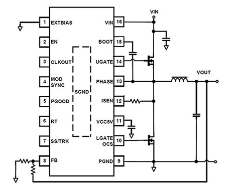
According to ISL8117’s data sheet, the PWM controller uses valley-current-mode modulation with adaptive-slope compensation to enable stable operation for a wide range of VIN and VOUT combinations, with no external compensation required. Additionally, system designers can also use the controller’s adjustable frequency up to 2 MHz to optimize power supply cost, size, and efficiency. The ISL8117 offers programmable soft-start and enable functions along with a power-good indicator for ease of supply rail sequencing and other housekeeping requirements. Also, as per the product data sheet, only about 10 external components are needed to complete the high step-down-ratio buck-converter solution with overvoltage/overcurrent/over temperature protections as shown in Figure 1. The PWM controller comes in space-conscious 16-lead QFN and HTSSOP packages. Both packages use an EPAD to improve thermal dissipation and noise immunity.

Figure 1: The ISL8117 integrates control circuit drivers for MOSFETs and protection circuits to simplify the design of high step-down-ratio buck converters. It requires few external components to complete the solution.
The efficiency of such converters is dependent on key parameters such as VIN/VOUT ratio, RDS(on) of power MOSFETs, switching frequency, and the inductor. If all other parameters are kept constant, the efficiency decreases as the VIN/VOUT ratio increases. For example, if the peak efficiency of the 48 V to 3.3 V DC/DC converter is about 85%, it will fall by several points when the output is around 1 V and the input is 48 V.
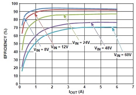
To evaluate this controller in real-world applications, Intersil has crafted two evaluation boards. The low-power evaluation board ISL8117EVAL1Z is designed for high-current applications. Its electrical parameters include 4.5 – 60 V input range, 600 kHz switching frequency, and 3.3 V output voltage at 6 A output current. The overcurrent protection set point in this design is 8 A (minimum) at ambient room temperature. A typical schematic used in this board for evaluating this controller is shown in Figure 2. Measured efficiency performance for this design with varying input voltage and fixed 3.3 V output across load variation is depicted in Figure 3.
Figure 2: Typical evaluation board schematic for a 4.5 – 60 V input and 3.3 V output at 6 A.

Figure 3: Efficiency versus output current for the high step-down-ratio buck converter in continuous-current mode (CCM). The output is 3.3 V.
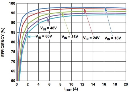
It is observed that the peak efficiency for a 48 V input is around 78%, which increases by more than 10 points when the input is dropped to 24 V. If the output is higher for the same input, the efficiency goes upwards as demonstrated in the second high-power evaluation board ISL8117EVAL2Z, which is designed for 18 – 60 V input and 12 V output at 20 A. This high-power board is designed to deliver over 200 W. A detailed schematic with bill of materials, which includes output-power MOSFETs and the inductor, is provided in the user guide along with the measured performance. Figure 4 illustrates the efficiency curve for the 12 V output board ISL8117EVAL2Z.

Figure 4: Efficiency versus load current for a continuous-current-mode buck converter with 18 – 60 V input range and 12 V output at 20 A.
From Figure 4 it is observed that when the input voltage is 48 V, the peak efficiency is around 95%, significantly higher than the 3.3 V output converter. With 12 V output, the input to output ratio is only 4:1 as compared to 14.5:1 for a 3.3 V output. Internally, using ISL8117, the company has demonstrated a 48 V input to 1 V output converter at 10 A with 200 kHz switching frequency. The switching frequency has been decreased to improve the overall efficiency of the design. Internal tests indicate that with external 5 V bias, the high step-down-ratio buck converter can offer 78% peak efficiency at full-load and 80% at mid-load.
More choices
Linear Technology is another supplier interested in tackling these issues. The company has released a 60 V synchronous step-down controller LTC3891 that is capable of realizing non-isolated high step-down-ratio buck converters with high efficiencies. Rated for a wide input range of 4 V to 60 V, the output voltage can be programmed from 0.8 V to 24 V. Minimum on-time for this part is 95 ns and the switching frequency range is 50 – 900 kHz. The package option is 20-lead QFN or HTSSOP. The part’s data sheet presents a design example that handles an input voltage range of 4 V to 60 V to deliver low output of 3.3 V at 5 A with high efficiency. Typical efficiency versus input voltage for 3.3 V output design with load current of 2 A is presented in Figure 5. It shows that the efficiency drops quickly as the input voltage increases.

Figure 5: Typical efficiency versus input voltage curve for a LTC3891-based high step-down-ratio buck converter. It shows that the efficiency drops quickly as the input voltage increases.
Similarly, TI has released TPS40170 to realize high step-down-ratio converter solutions. A 60 V-wide input synchronous PWM buck controller, the TPS40170 offers an on-time of 50 ns with programmable frequency range of 100 kHz to 600 kHz and voltage-mode control with input-voltage fed-forward compensation. It comes in a 20-pin VQFN package.
In summary, as more and more suppliers see an opportunity in this space, designer’s choices for building high step-down-ratio buck converters is increasing. While some prefer to deliver a complete solution from 48 V bus voltage to the low-processor voltage, others have decided to provide high-voltage synchronous buck controllers for the same. Concurrently, eGaN FETs have also entered the space to compete with silicon parts.
For more information on the products discussed in this article, use the links provided to access product pages on the Digi-Key website.
References
- “High-Step-Down-Ratio Buck Converters for Intermediate Bus Architectures” by Ashok Bindra, Electronic Products, Digi-Key TechZone, April 2013
- “High Step-Down-Ratio Buck Converters With eGaN Devices,” by Johan Strydom, Efficient Power Conversion, El Segundo, Calif. and Bob White, Embedded Power Labs, Highlands Ranch, Colo., How2Power Today, Nov. 23, 2010
免责声明:各个作者和/或论坛参与者在本网站发表的观点、看法和意见不代表 DigiKey 的观点、看法和意见,也不代表 DigiKey 官方政策。


